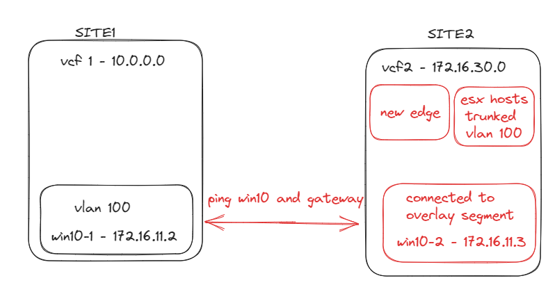
Layer 2 (L2) edge bridge allows virtual machines to communicate via layer 2 and establishes a bridge between sites. This can be use for migrating virtual machines between sites for example a vm that might be on normal vlan port groups/nsx-v to an overlay network on nsx-t.
I have setup two VCF environments, one vm is on a normal vlan port group vlan 100 and the other I will put on the new overlay segment I am going to create. Then I will test connectivity between the vms and gateway.
High-level tasks
1. ESXi hosts are trunked with the vlan of the virtual machine (Using vlan 100 in my lab)
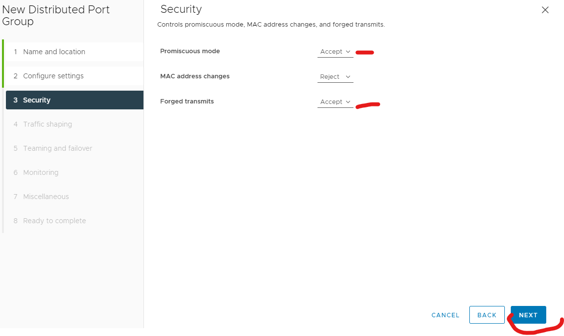
2. Create two port group with vlan trunking with promiscuous mode and forged transmits accepted, and uplinks active and standby on them.
3. Run the command to enable reverse filter on the ESXi host where the Edge VM is running
4. Deploy Edge on the destination site or the new segment location your using for overlay
5. Add edge(s) to cluster
6. Create edge bridge profile
7. Create overlay segment for the virtual machine
8. Add edge bridge to the overlay segment
9. Assign edge profile vlan transport zone and vlan id
10. Put vm on new overlay segment
11. Test vms can ping each other across the vcf environments and gateway
1. Trunk your vlan to the ESXi hosts via your switch
2. Create two port group with vlan trunking, with promiscuous mode and forged transmits accepted, and uplinks active and standby at my destination.
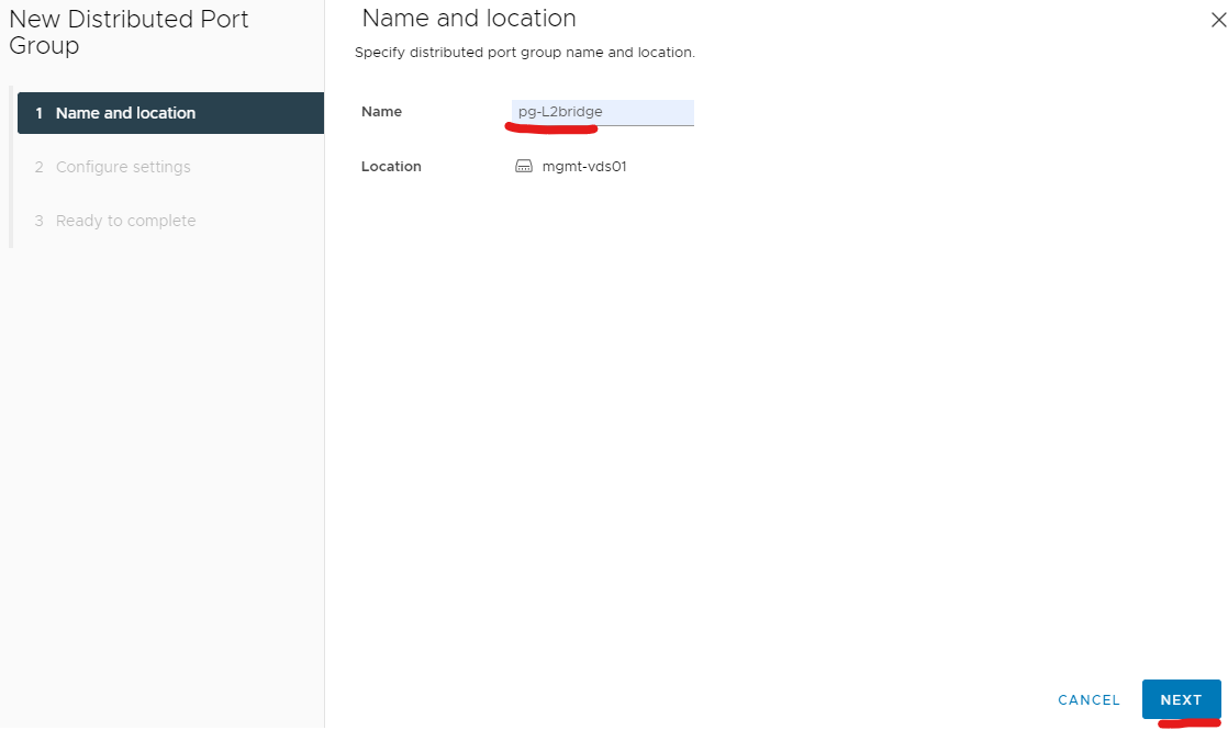
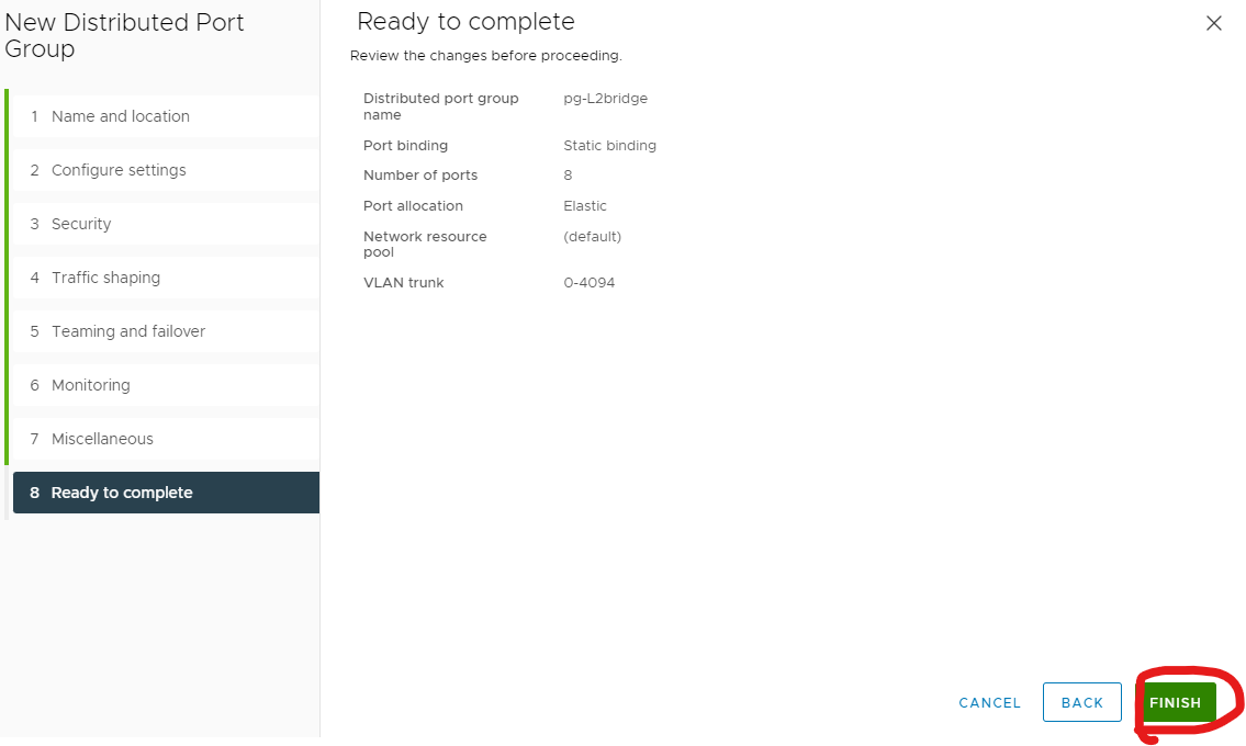
Create a new port group on your dvs

Give your port group a meaningful name.
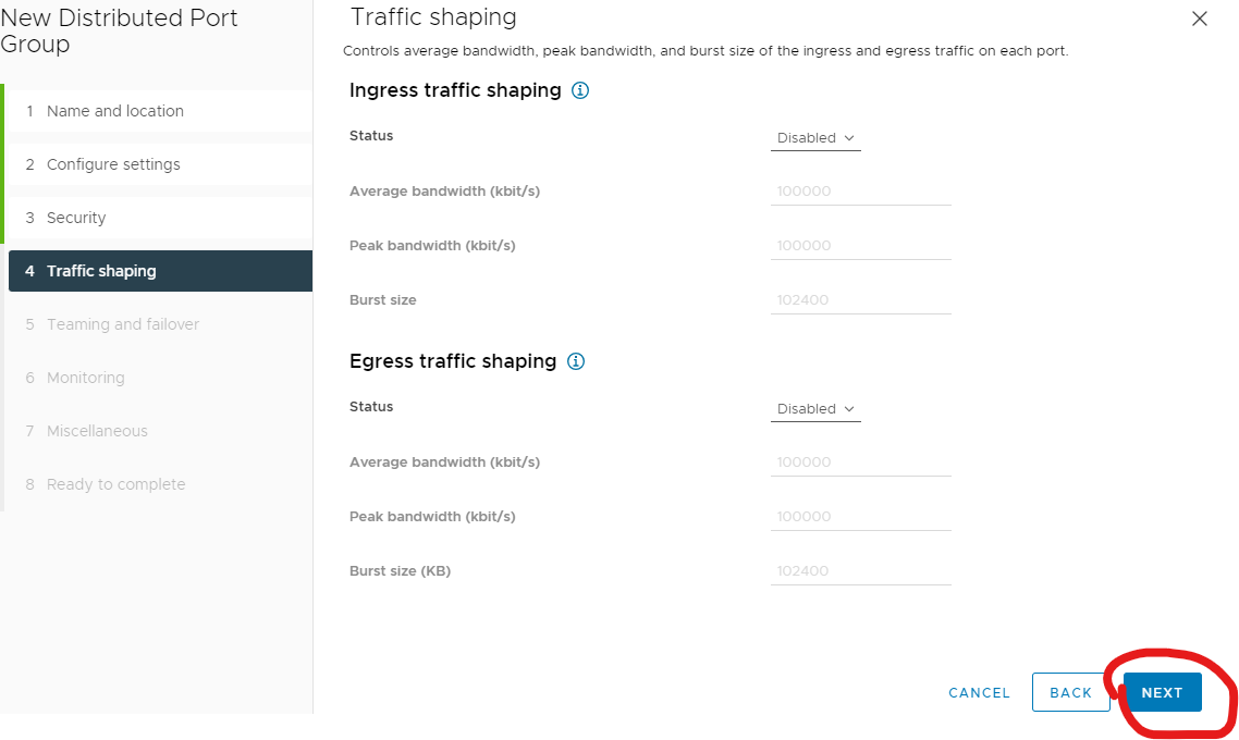
Change vlan to VLAN trunking and click customize.
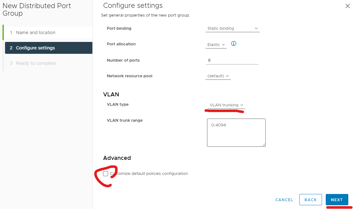
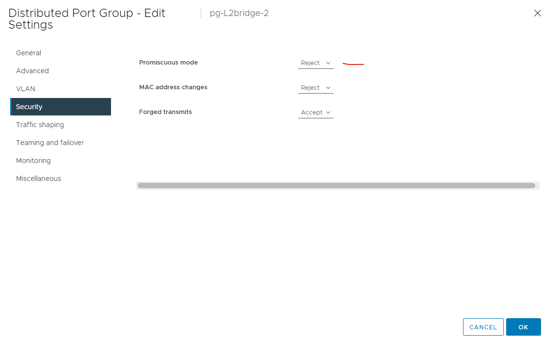
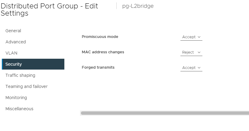
Change promiscuous mode and forged transmits to accept.
Next
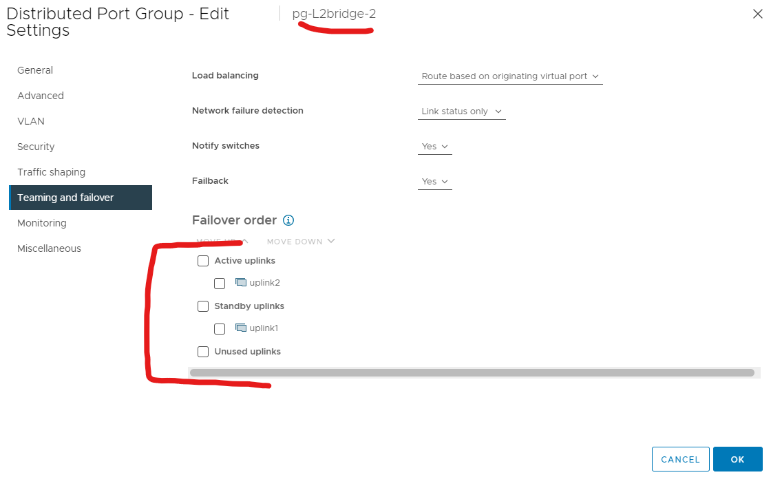
Change first port group to uplink1 as active and uplink2 as standby.
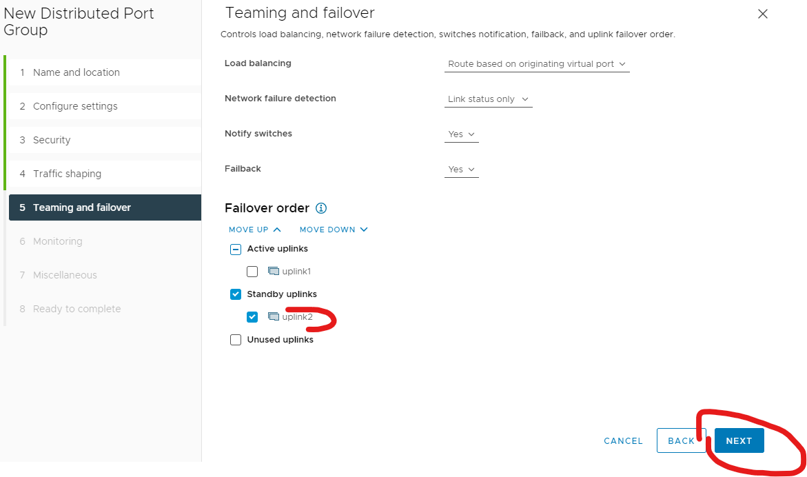
Next
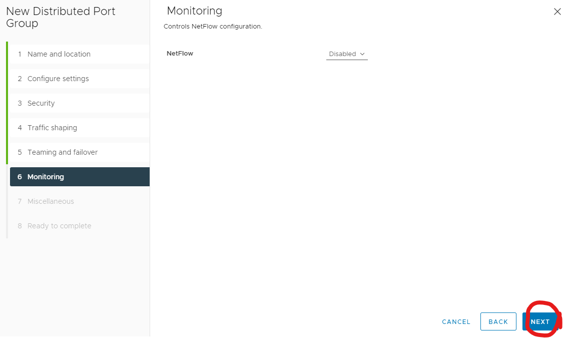
Next
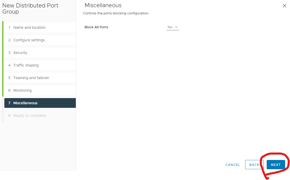
Finish
Create another port group but uplink2 as active and uplink1 as standby.
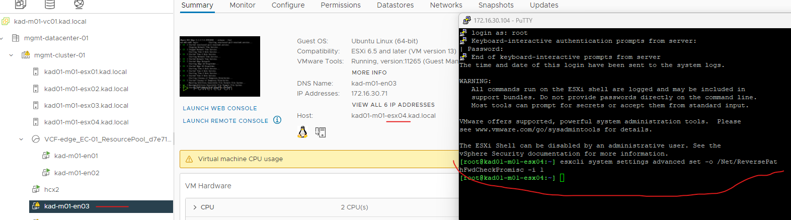
 3. Run the command to enable reverse filter on the ESXi host where the Edge VM is running.
SSH to the host running your edge and run the below.
esxcli system settings advanced set -o /Net/ReversePathFwdCheckPromisc -i 1
disable and enable promiscuous mode on both port groups.
disable promiscuous mode first.
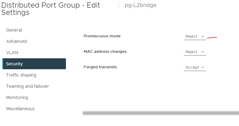
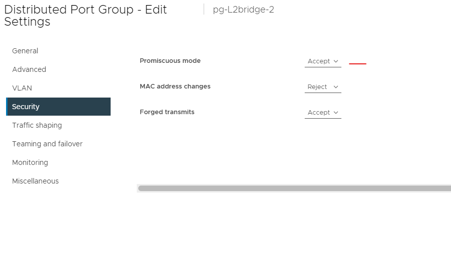
Then enable back promiscuous mode back.
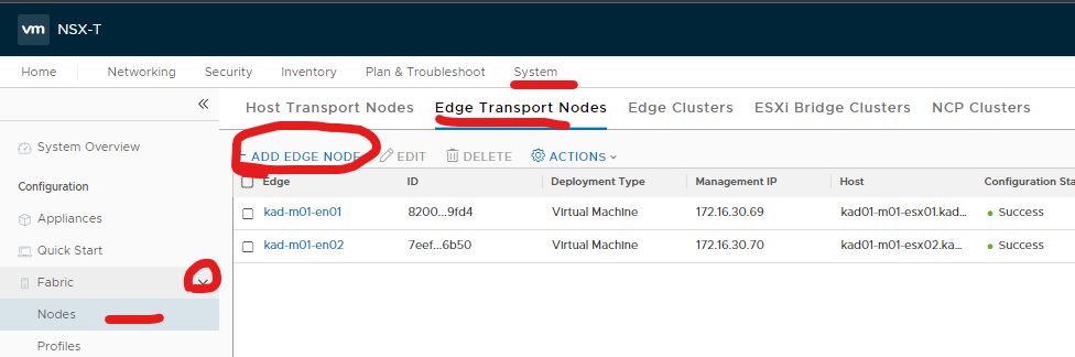
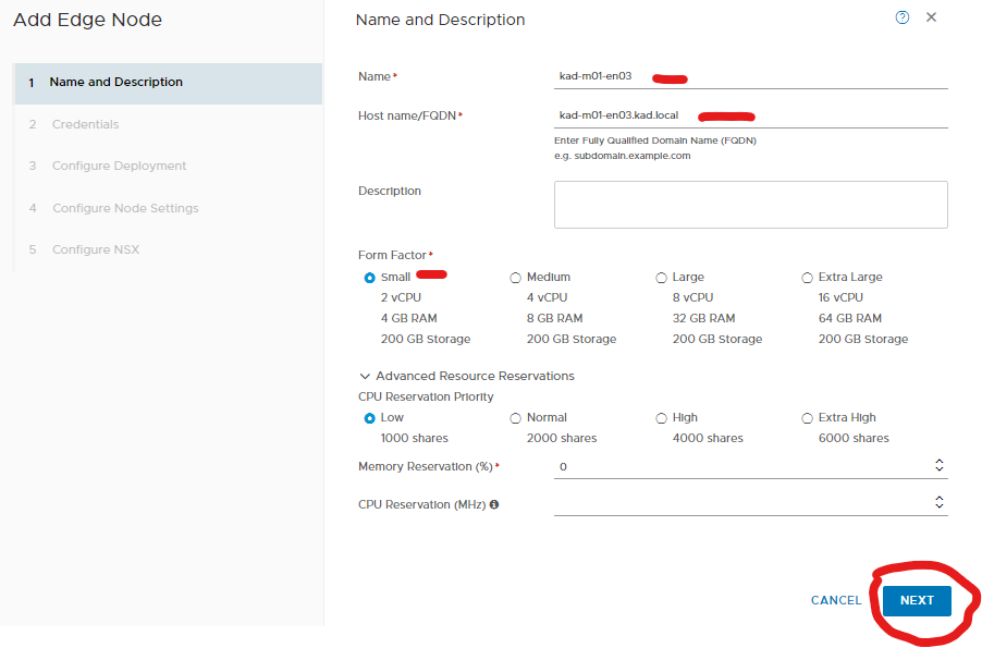
4. Deploy edge on destination site
Put in your name, FQDN and size.
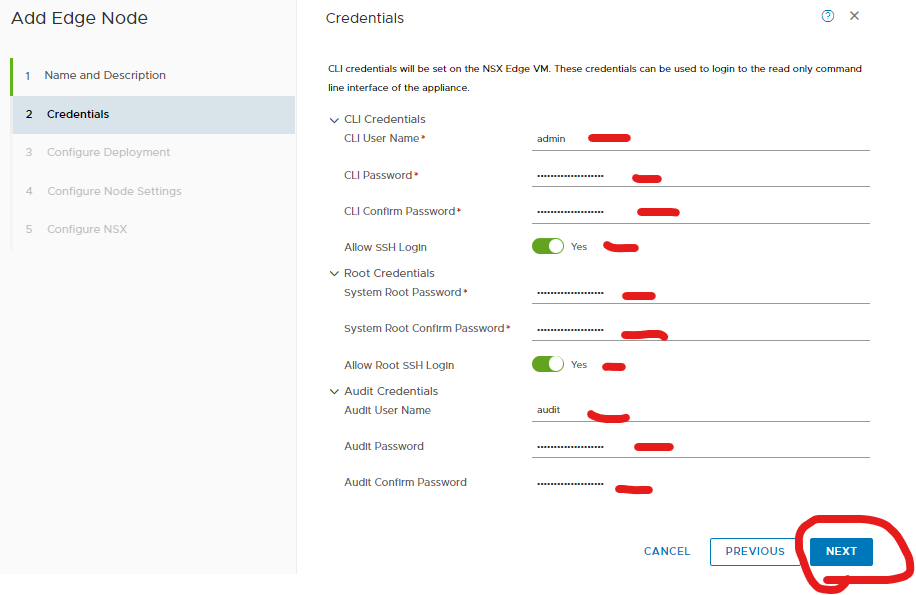
Put in your credential details.
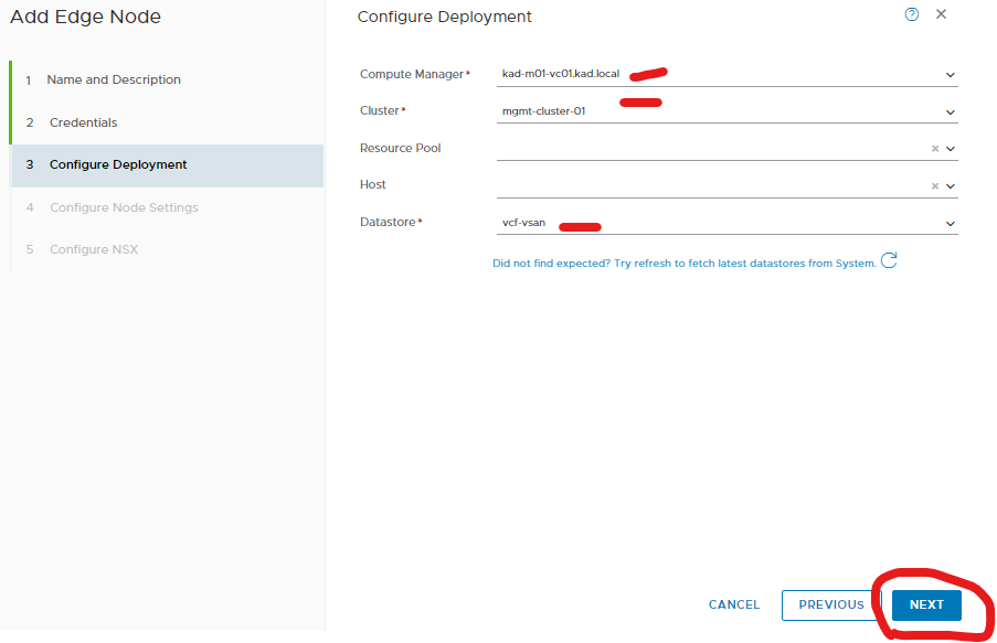
Select your vcenter, cluster and datastore.
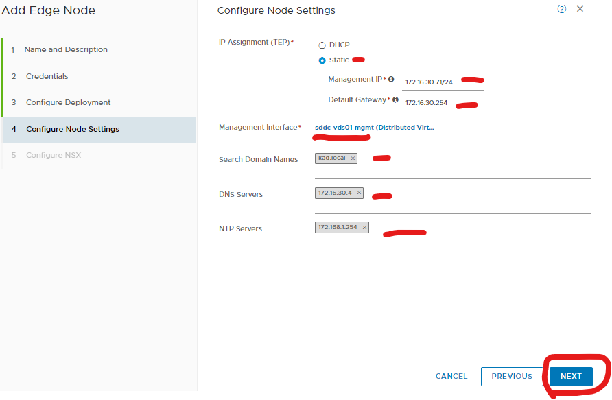
Put in your management details of your edge.
Add your transport zones one for vlan and one for overlay
I am using the existing uplink profile.
Put in your TEP details. (Same range as my other teps)
Then assign your uplinks to the new port groups you created.
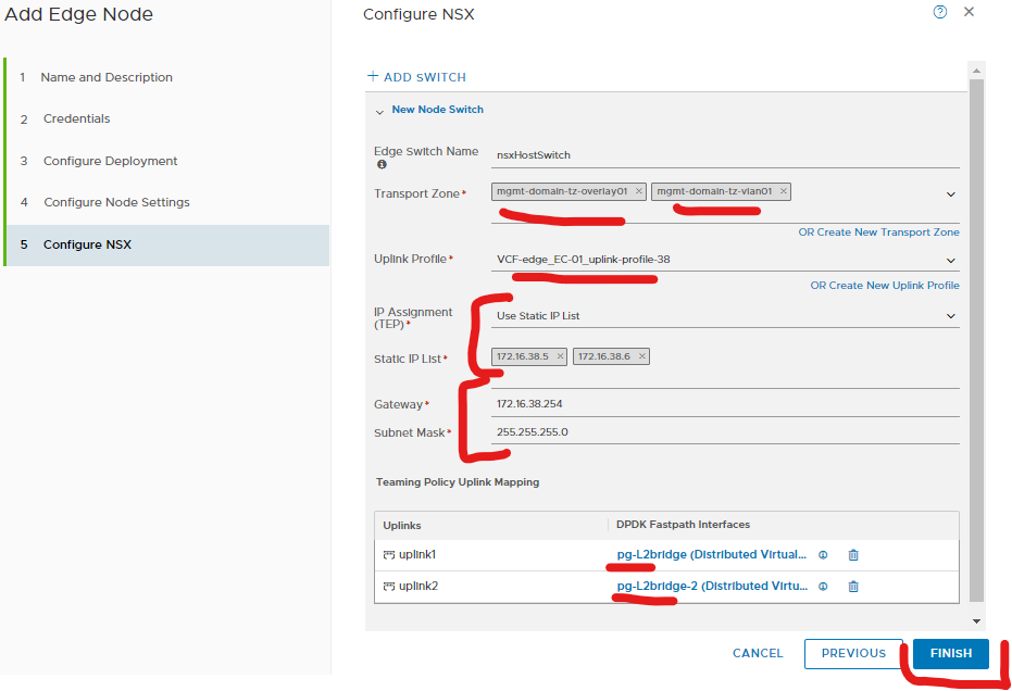
For prod I recommend two edges.
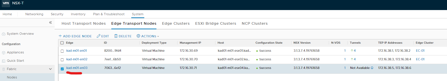
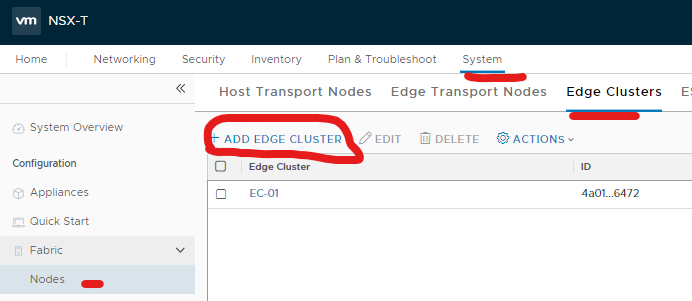
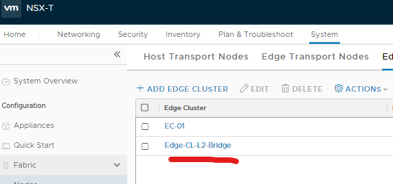
5. Add edge(s) to cluster
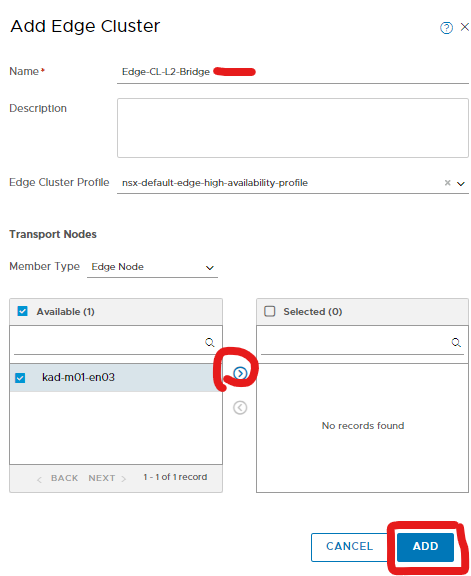
Add that edge into a new edge cluster.
Give it a name and select your edge(s) and click the right arrow
Click add.
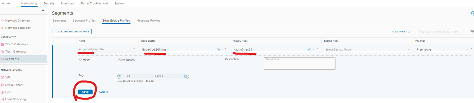
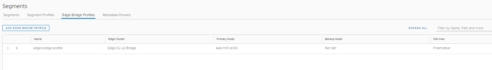
6. Create edge bridge profile

Since this is a lab, I am not using a backup edge node.
Give it a name, select your new edge cluster and then select your primary and backup node edge.
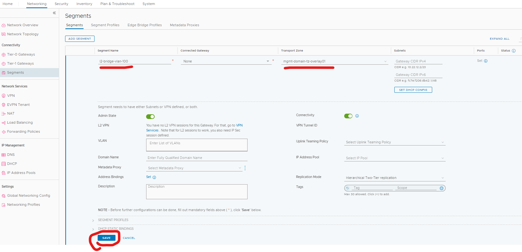
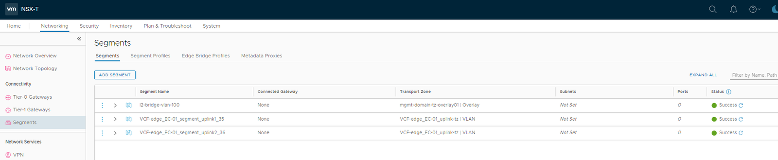
7. Create overlay segment for the virtual machine
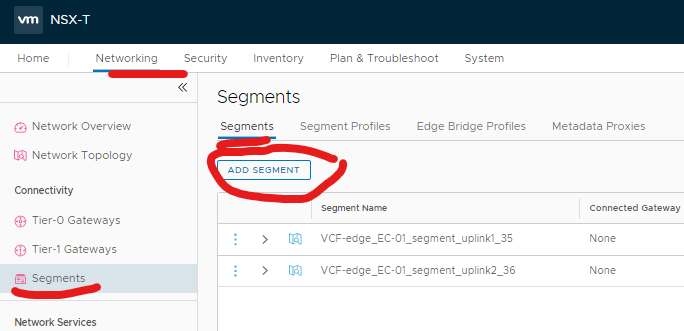
Type a meaningful name for the segment and select the ‘overlay’ transport zone you used during your edge deployment.
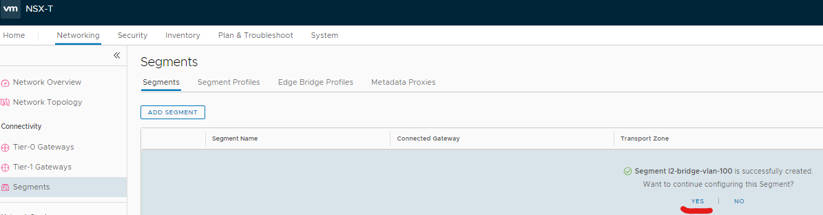
8. Add edge bridge to the overlay segment
Click yes to continue configuring.
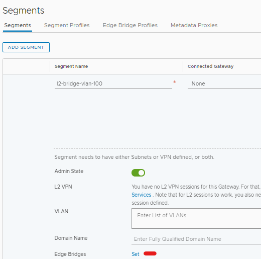
Click Set next to edge bridges.
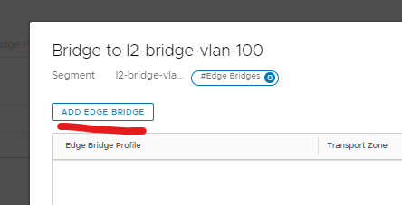
Add edge bridge.
9. Assign edge profile, ‘vlan’ transport zone and vlan id
From the drop down select the edge profile, select the ‘vlan’ transport zone you used in your edge deployment and add vlan id.
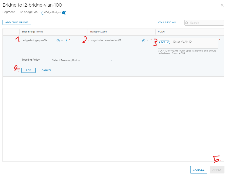
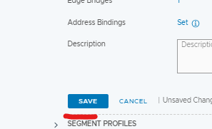
Save
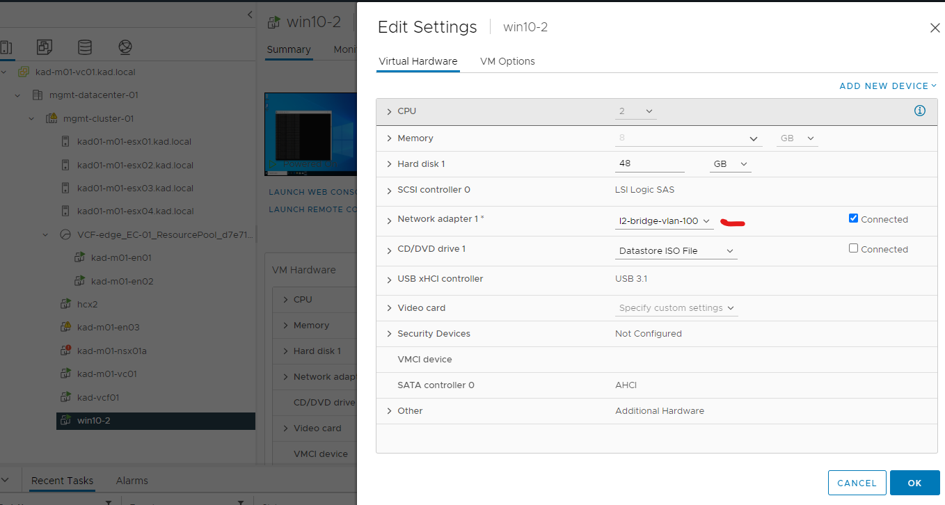
10. Put vm on the new overlay segment
Edit the virtual machine you want on the new overlay segment and change network.
11. Test vms can ping each other across the vcf environments and gateway.
Ping test gateway
Ping test to win10-1 on other vcf environment

Done
Official VMware documentation
Additionally if you don’t want promiscuous mode on you can turn on mac learning on the port group, I used the following commands.
run this in your powershell for get-maclearn command – https://github.com/lamw/vmware-scripts/blob/master/powershell/MacLearn.ps1
Set-ExecutionPolicy Unrestricted
Set-PowerCLIConfiguration -InvalidCertificateAction Ignore -Confirm:$false
Connect-VIServer -Server 172.16.30.62
Get-MacLearn -DVPortgroupName @(“pg-L2bridge”)
Get-MacLearn -DVPortgroupName @(“pg-L2bridge-2”)
Set-MacLearn -DVPortgroupName @(“pg-L2bridge”) -EnableMacLearn $true -EnablePromiscuous $false -EnableForgedTransmit $true -EnableMacChange $false
Set-MacLearn -DVPortgroupName @(“pg-L2bridge-2”) -EnableMacLearn $true -EnablePromiscuous $false -EnableForgedTransmit $true -EnableMacChange $false
