1. Create transport zone for overlay and vlan
2. Create two uplink profiles for edge and hosts
3. Create Host Node profile and assign to ESXi cluster
Key information
- one DHCP pool for host teps – vlan 33
- static ip allocation for edge tep vlan 63
- dhcp for vlan 33 / network 172.16.33.0/24 / Gateway 172.16.33.254
- vlan 63 /network 172.16.63.0/24 / gateway 172.16.63.254
- Esxi host uplink profile config – vlan 33
default teaming / Load Balance Source /uplink-1,uplink-2
uplink-1 / Failover Order / uplink-1
uplink-2 / Failover Order / uplink-2
uplink-1-failover_order / Failover Order / uplink-1 / uplink-2
uplink-2-failover_order / Failover Order / uplink-2 / uplink-1
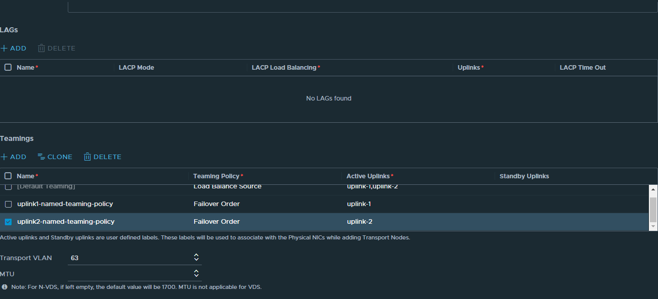
- edge uplink profile config – vlan 63
default teaming / Load Balance Source / uplink-1,uplink-2
uplink1-named-teaming-policy / Failover Order / uplink-1
uplink2-named-teaming-policy /Failover Order /uplink-2
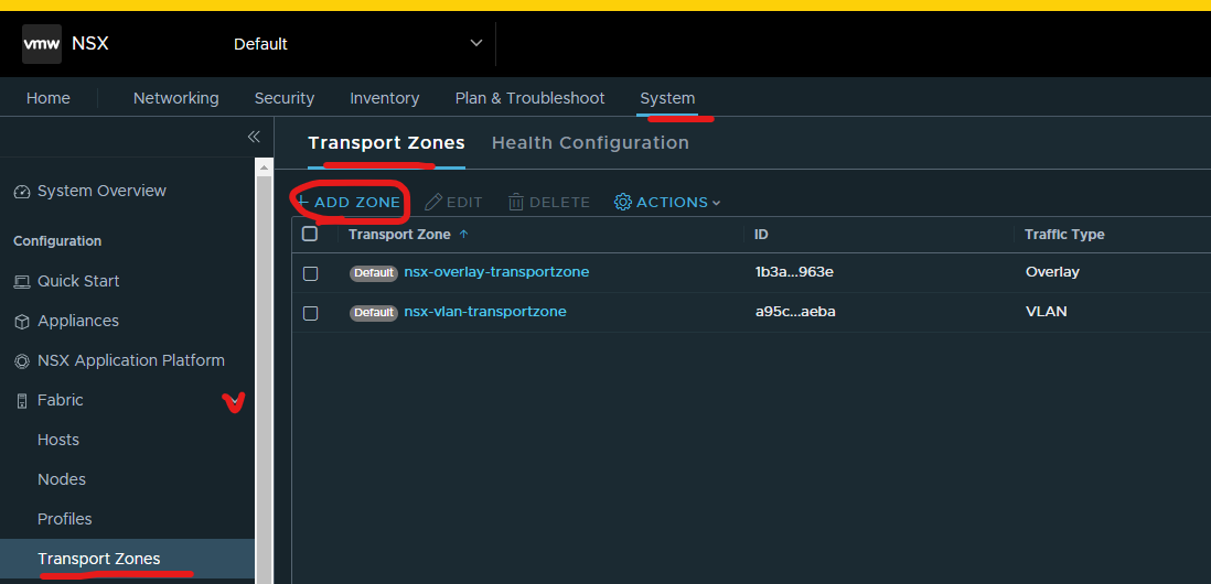
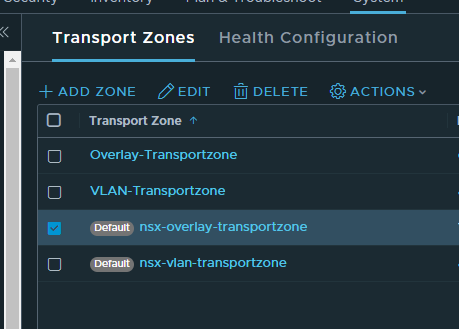
1. CREATE TRANSPORT ZONE FOR OVERLAY AND VLAN
Login to NSX-T Manager > click system > expand fabric > click transport zones > click transport zones tab > click add zone
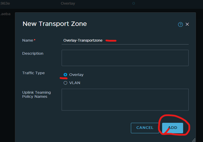
Type in a meaningful name for overlay transport zone > select overlay > click add
Click add zone
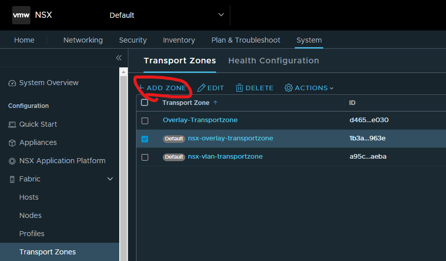
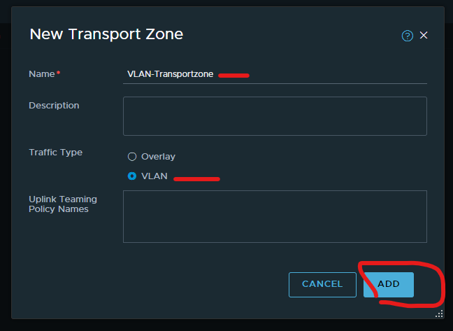
Type in a meaningful name for VLAN transport zone > select VLAN > click add
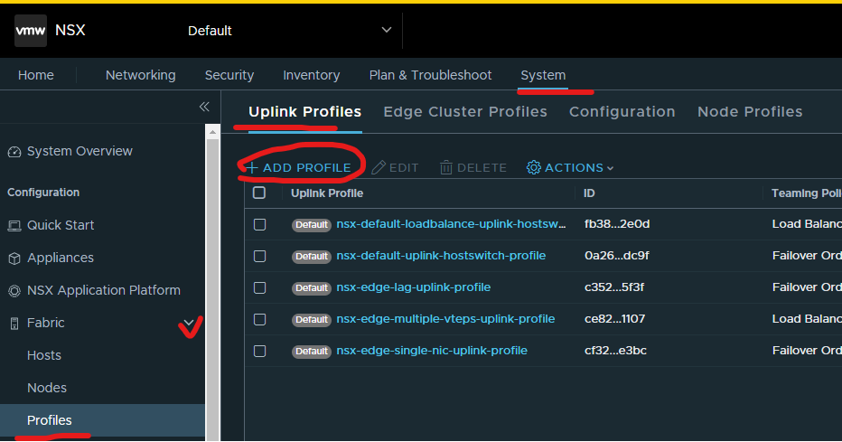
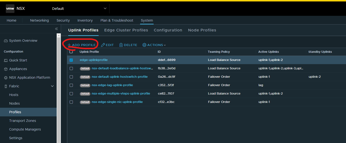
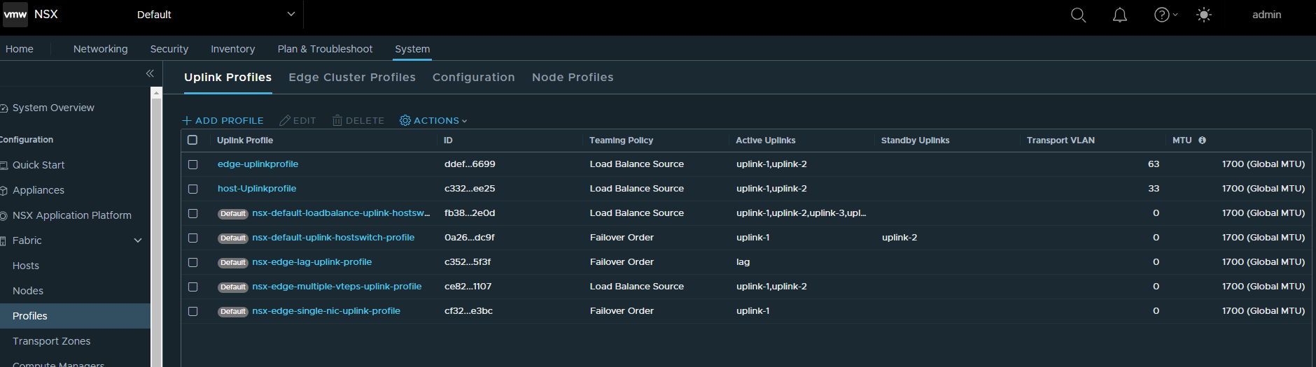
2. CREATE TWO UPLINK PROFILES FOR EDGE AND HOSTS
Login to nsx-t manager > click system > expand fabric > click profiles > under Uplink profile tab > click add profile.
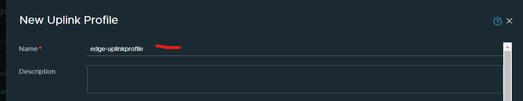
Give your edge uplink profile a name
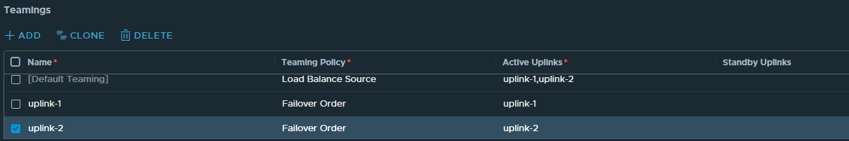
Enter teaming configuration using ADD button
default teaming / Load Balance Source / uplink-1,uplink-2
uplink1-named-teaming-policy / Failover Order / uplink-1
uplink2-named-teaming-policy /Failover Order /uplink-2
Then enter the transport VLAN
Click add
Click Add profile
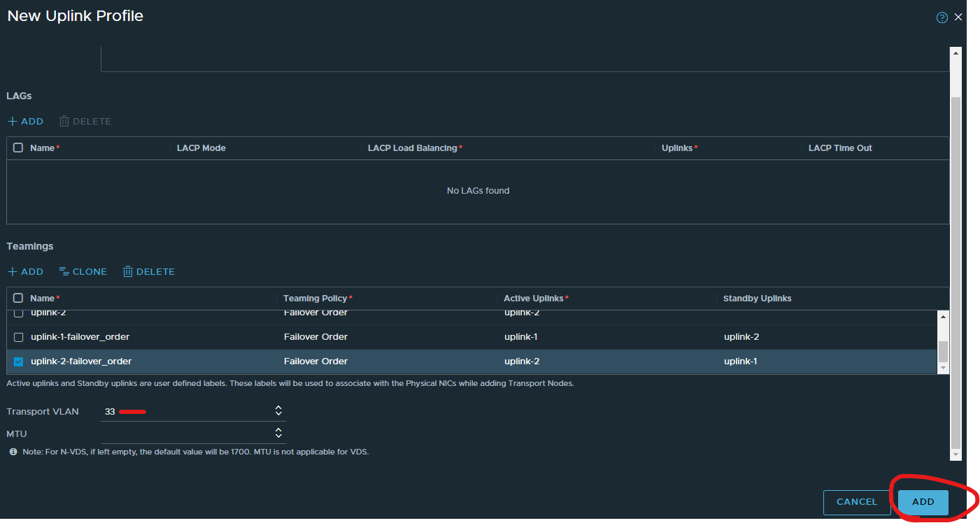
Give your host uplink profile a name

Enter teaming configuration using ADD button.
default teaming / Load Balance Source /uplink-1,uplink-2
uplink-1 / Failover Order / uplink-1
uplink-2 / Failover Order / uplink-2
uplink-1-failover_order / Failover Order / uplink-1 / uplink-2
uplink-2-failover_order / Failover Order / uplink-2 / uplink-1
Then enter the transport VLAN
Click add

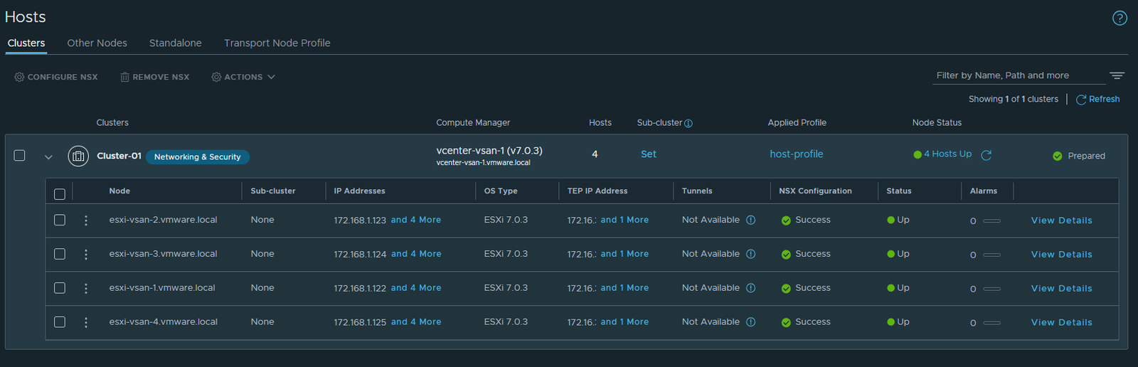
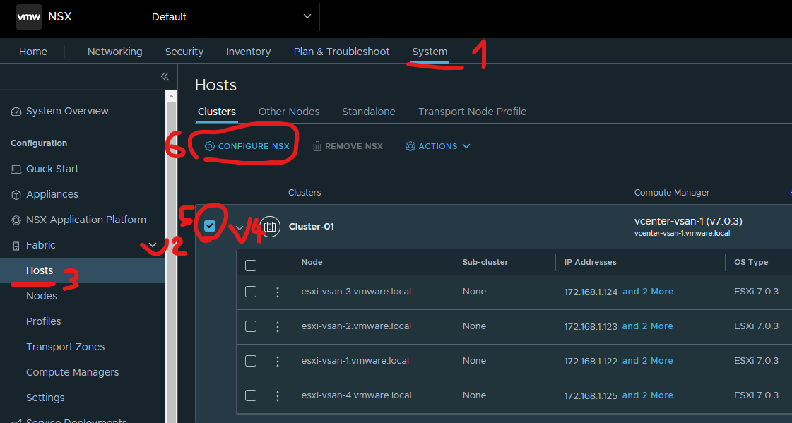
3. CREATE HOST NODE PROFILE AND ASSIGN TO ESXI CLUSTER
Click system > expand fabric > click hosts > click clusters tab > tick the box next to your cluster name > click configure nsx
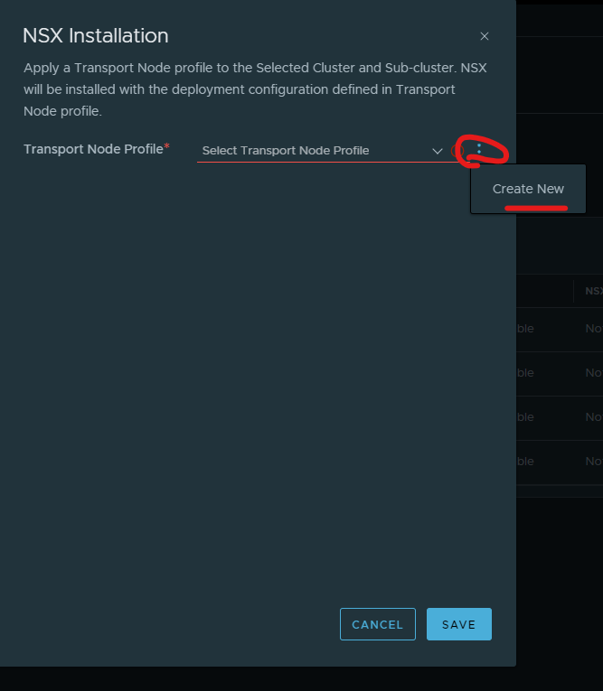
Click the ellipsis > click create new
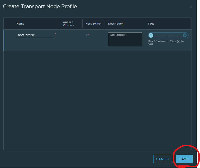
Give your host profile a name > click set.
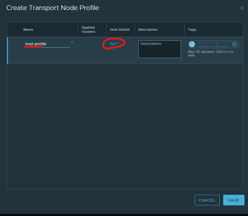
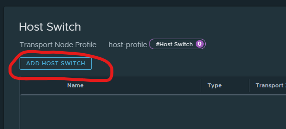
Click Add host switch
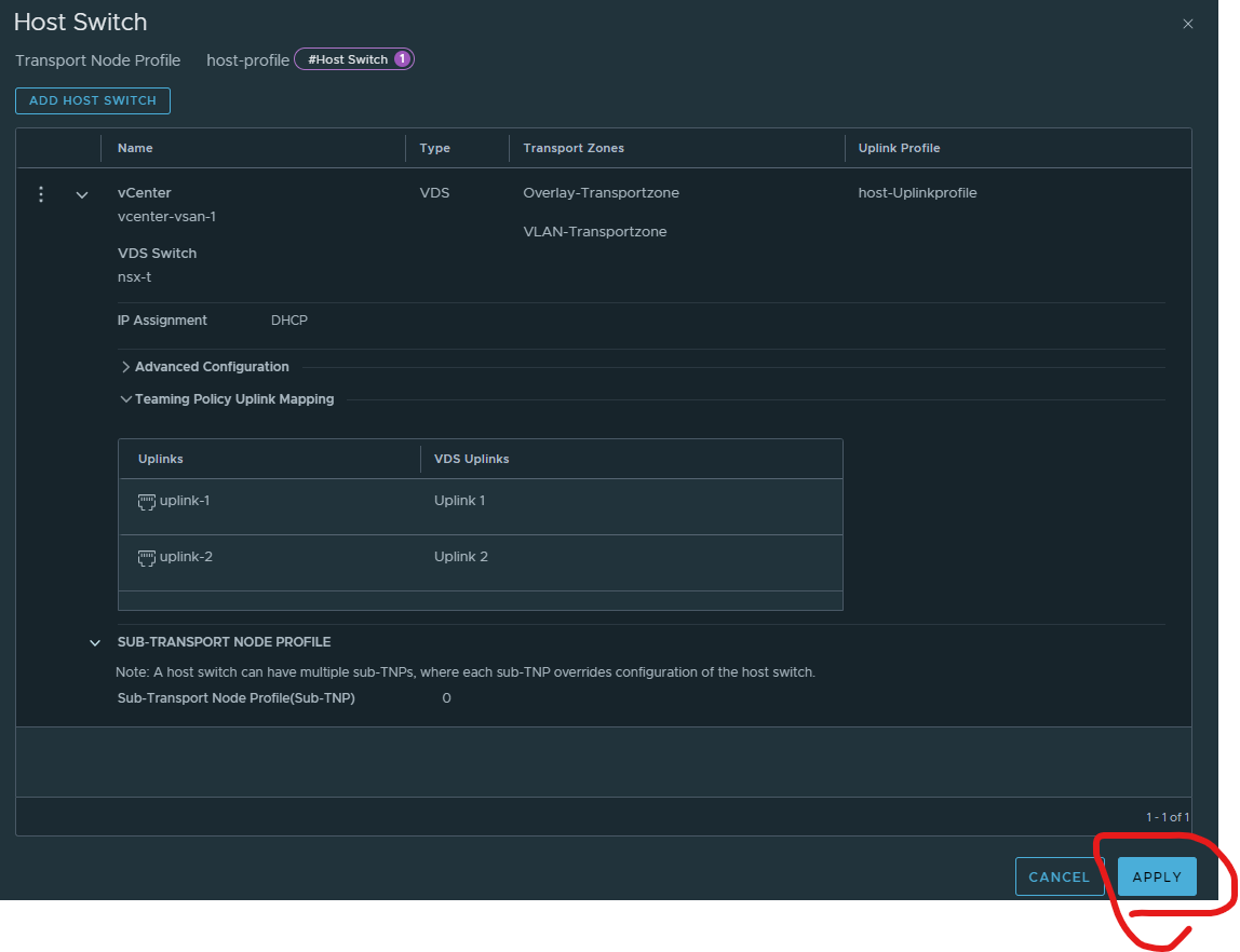
Select your vCenter > Select your overlay and vlan transport zones > select your host uplink profile > select your vds > select use dhcp > next to uplink1 and 2, select uplink 1 and uplink 2 > click add

Click apply
Click save
Click save
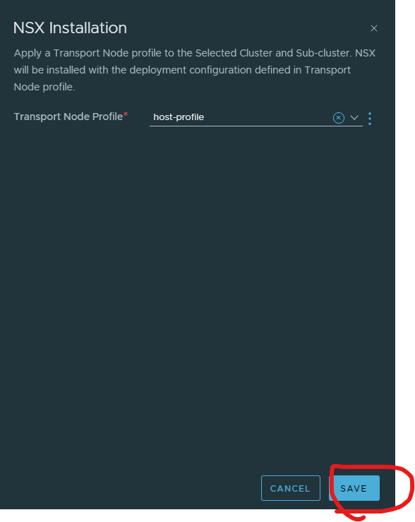
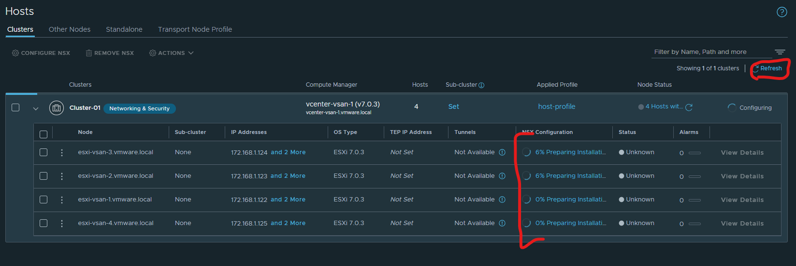
Done – took about 15 minutes.