Description
A segment is a logical switch that VMs can connect to. A tier-1 gateway routes traffic between segments. A tier-0 gateway connects tier-1 gateways to a physical router so that segments have external connectivity.
Diagram

Important Information
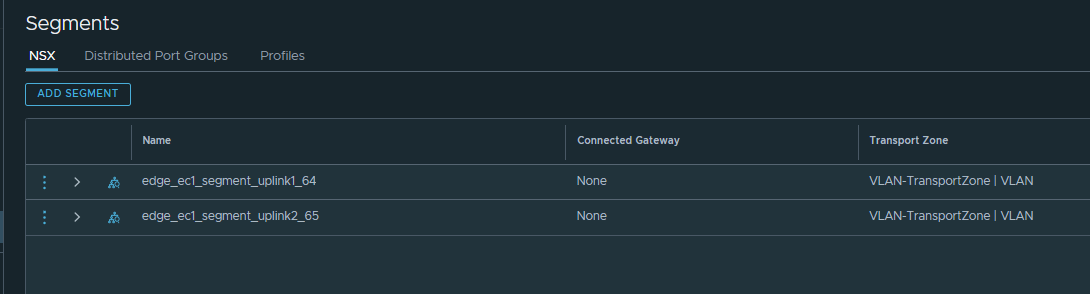
- Segment 1 – edge_ec1_segment_uplink1_64
- Segment 2 – edge_ec1_segment_uplink2_65
- vlan 64- bgp IP address 172.16.64.254/24
- vlan 65- bgp IP address 172.16.65.254/24
- Remote AS Cisco – 65000
- Local AS NSX – 65002
- edge1 uplink 1 – 172.16.64.1
- edge2 uplink 1 – 172.16.64.2
- edge1 uplink 2 – 172.16.65.1
- edge2 uplink 2 – 172.16.65.2
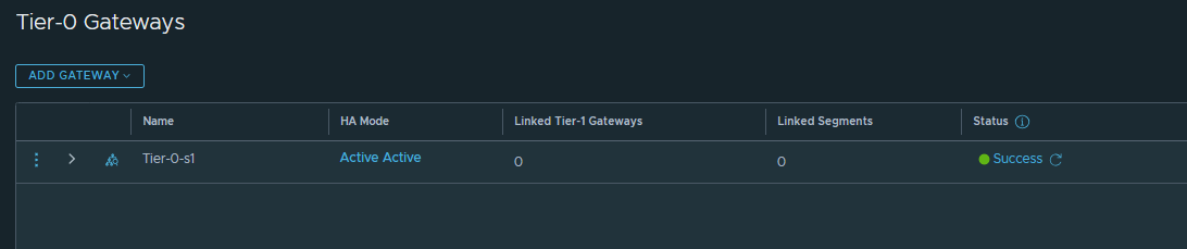
- Tier-0-s1
- Tier-1-s1
High-level steps
Step1 – create edge segments (This vlan is what your router uses, we will be using bgp routing protocol) two vlan segment on vlan 64 and 65
Step 2 – Create T0 gateway.
Set active/ active, set edge cluster 1, Setup interfaces, set local AS, set bgp neighbours, add route filter, add route re-distribution.
Step 4 – Create T1 gateway
Connect to T0, set edge cluster 1, enable standby relocation, enable routing, enable route advertisements.
Step 5 – Testing north/south traffic
Create overlay segment, assign to vm, ping router bpg ip
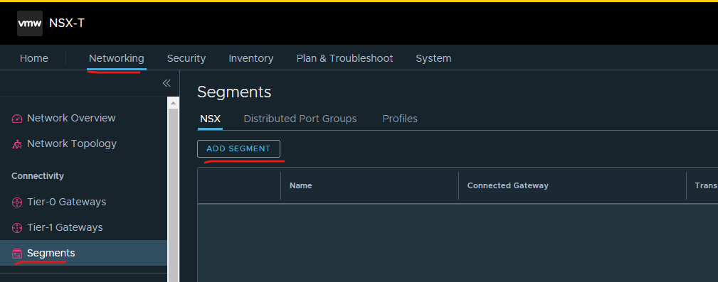
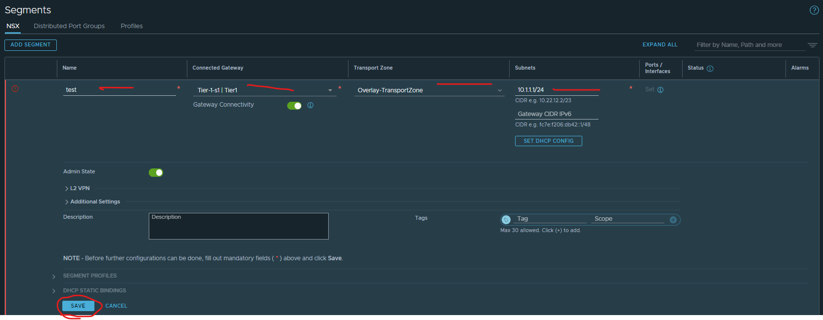
CREATE SEGEMENTS
Login to nsx-t manager > click networking > click segments > click add segment
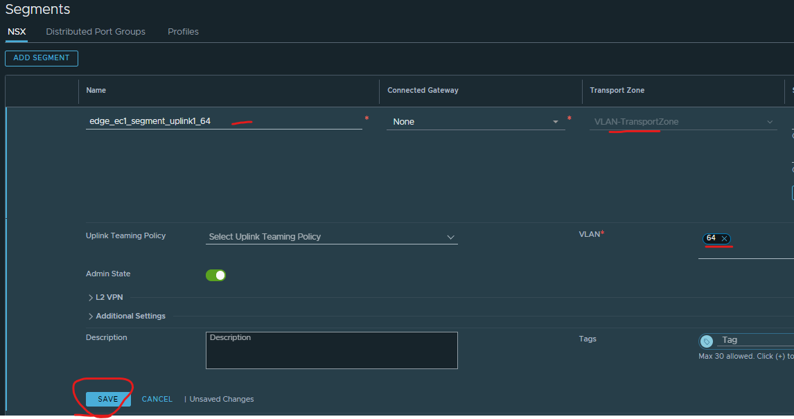
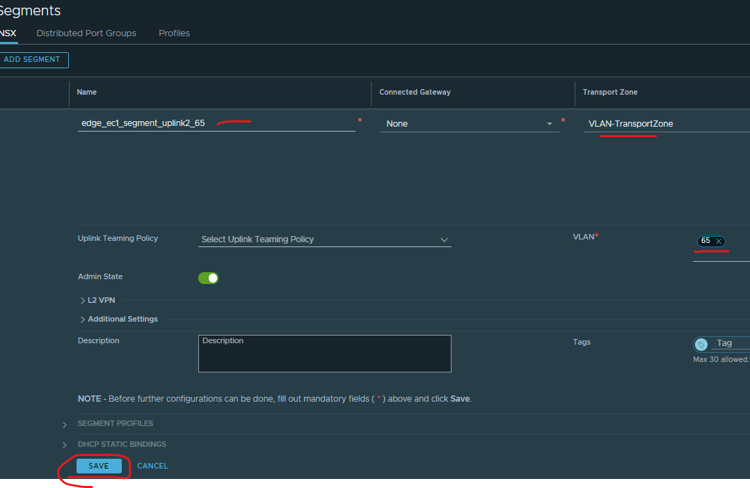
Give your first segment a name, put the vlan id ‘64’ in it, so it easily to identity > select vlan transport zone > put in the vlan id > click save
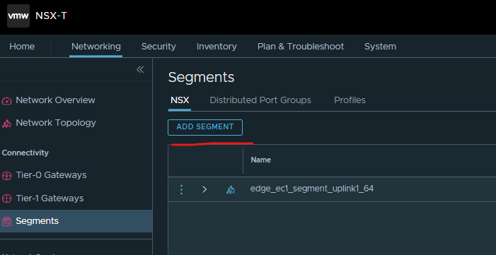
Click add segment
Give your second segment a name, put the vlan id ’65’ in it, so its easily to identity > select vlan transport zone > put in the vlan id > click save
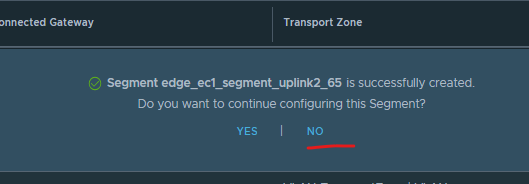
Click no
CREATE TIER 0 WITH BGP
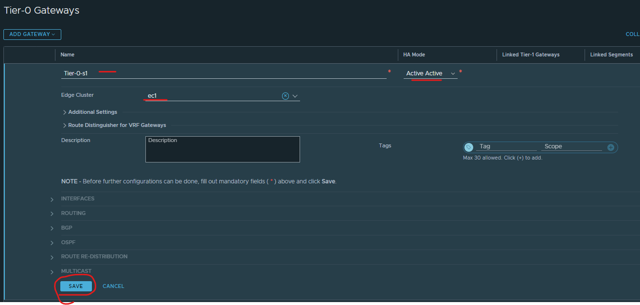
Click networking > click Tier-0 gateway > Click add gateway > click tier-0

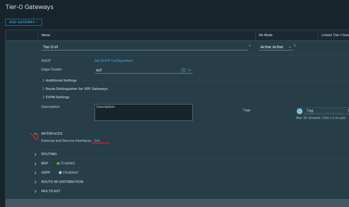
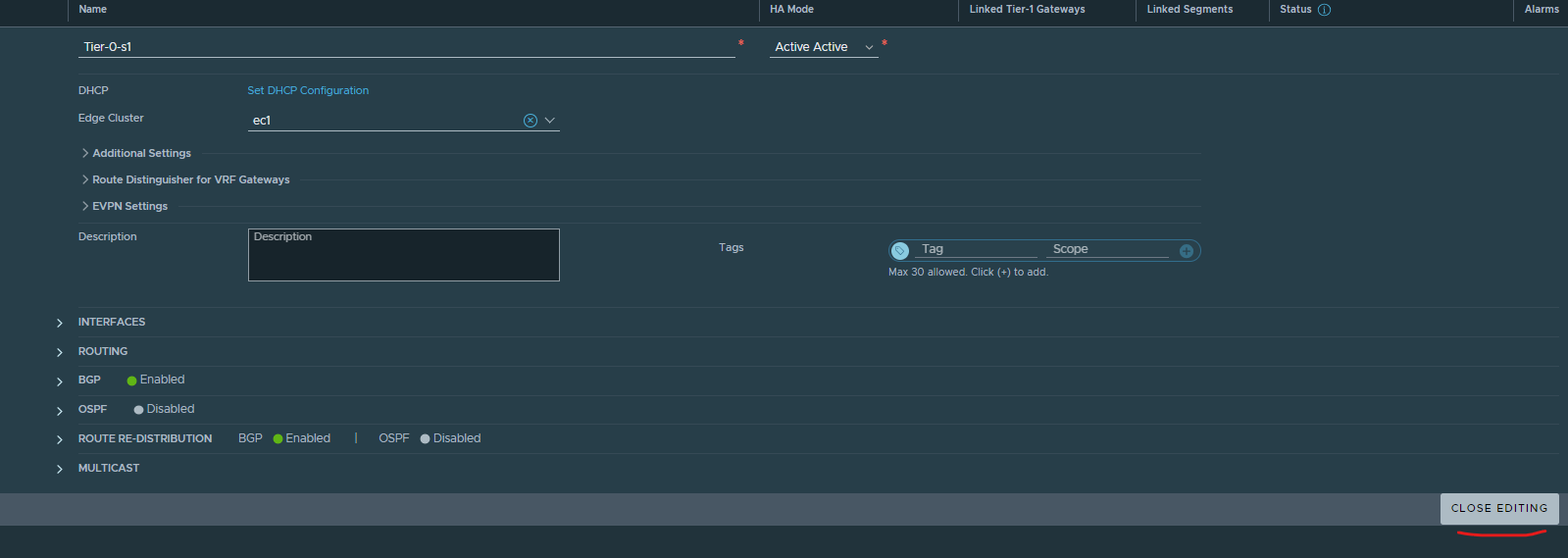
Give T0 a meaningful name > HA mode Active / Active > Select edge cluster 1 > Click save
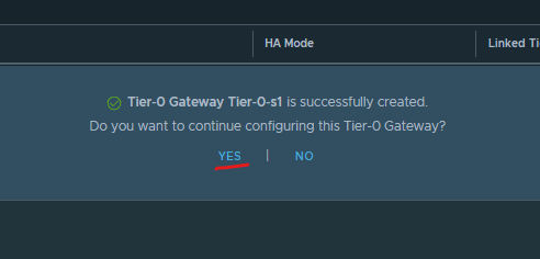
Click Yes
Expand interfaces > click set
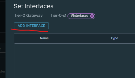
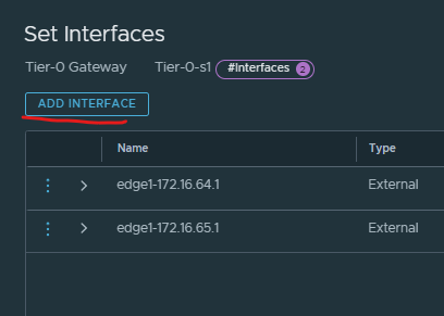
Click add interface (you will have four of them)
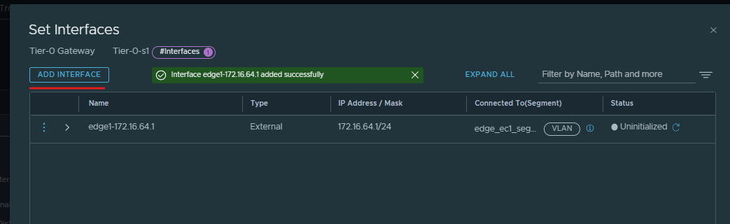
Enter an interface name – use the edge name and ip so it is easy to identify.
Enter ip address of the first interface.
Connect to the segment (make sure ip address and segment vlan match)
Example edge1 – ip 172.16.64.1 – segment ec1 64
Select edge node 1
Click save

Click add interface
Enter an interface name – use the edge name and ip so it is easy to identify.
Enter ip address of the second interface.
Connect to the segment (make sure ip address and segment vlan match)
Example edge1 – ip 172.16.65.1 – segment ec1 65
Select edge node 1
Click save.

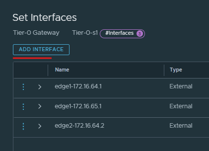
Click add interface
Enter an interface name – use the edge name and ip so it is easy to identify.
Enter ip address of the third interface.
Connect to the segment (make sure ip address and segment vlan match)
Example edge2 – ip 172.16.64.2 – segment ec1 64
Select edge node 2.
Click save.

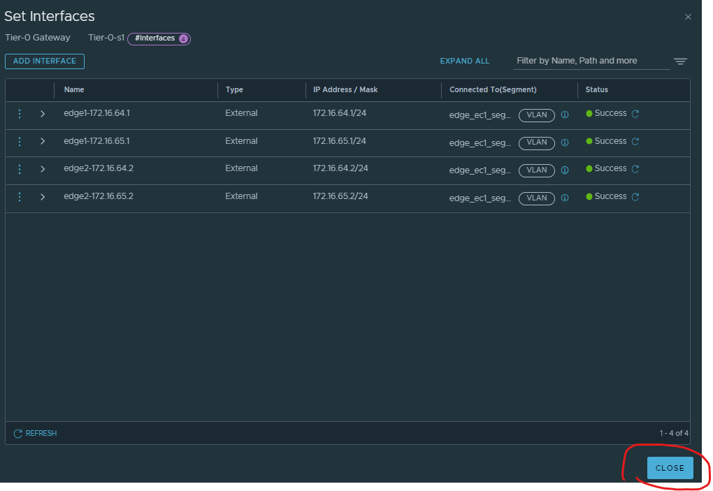
Click add interface
Enter an interface name – use the edge name and ip so it is easy to identify.
Enter ip address of the fourth interface.
Connect to the segment (make sure ip address and segment vlan match)
Example edge2 – ip 172.16.65.2 – segment ec1 65
Select edge node 2.
Click save.

Click close
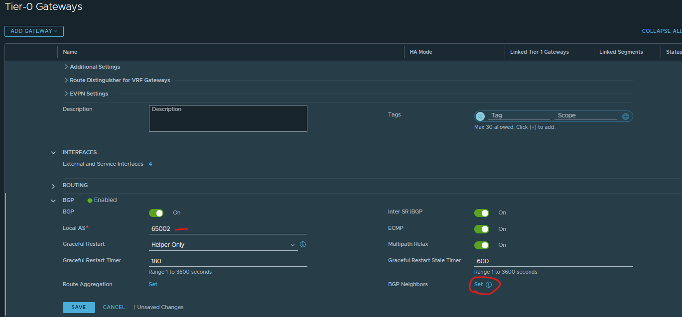
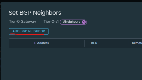
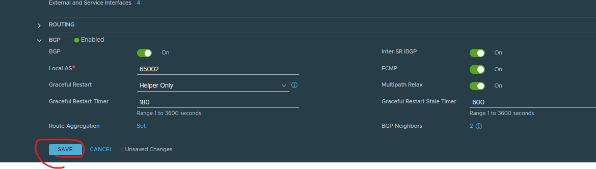
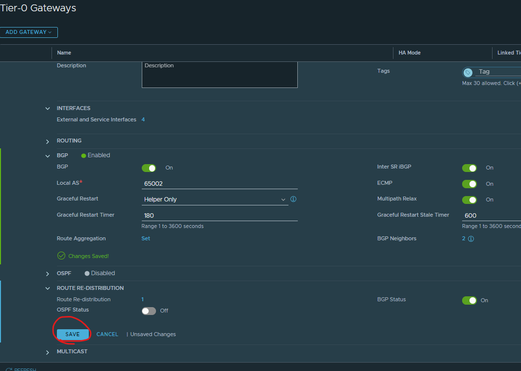
Expand bgp > enter local AS (your nsx bgp) > click set next to BGP neighbours
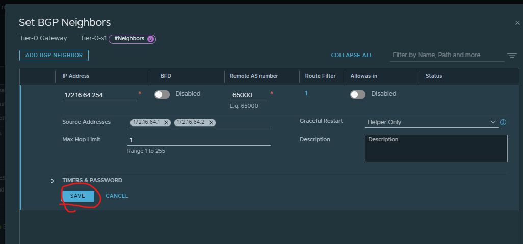
Click add bgp neighbour
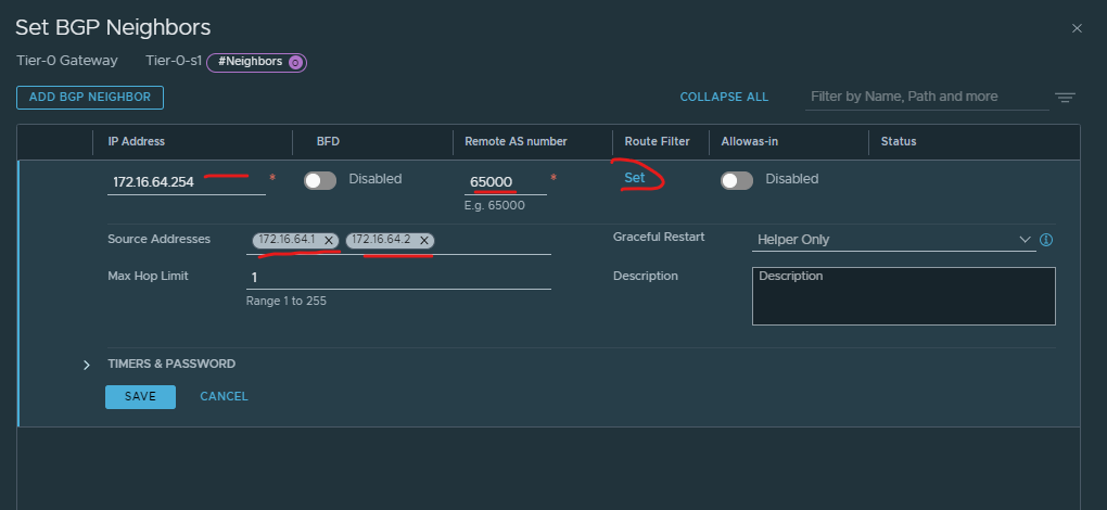
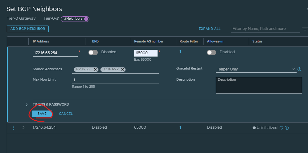
Enter ip of your remote bgp (so your router) > enter bgp of the remote AS > put in the ip address of the sources address ‘interface ip’ matching the same subnet as the router bgp ip > click route filter
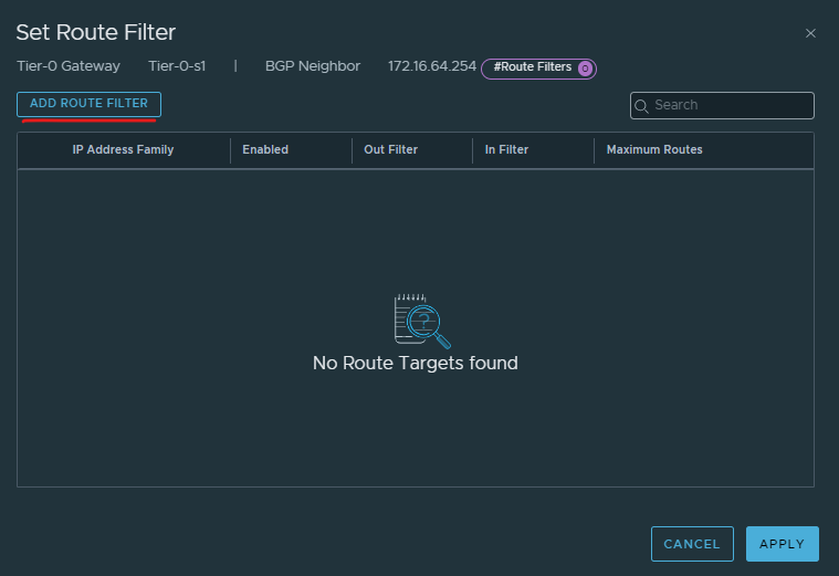
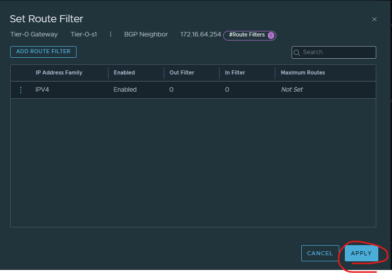
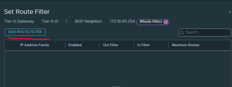
Click add route filter
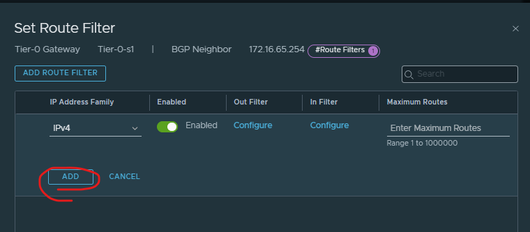
Ensure IPv4 and enabled > click add
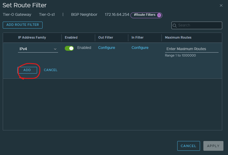
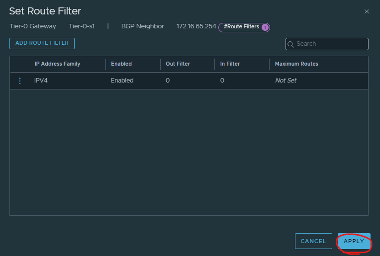
Click apply
Click save
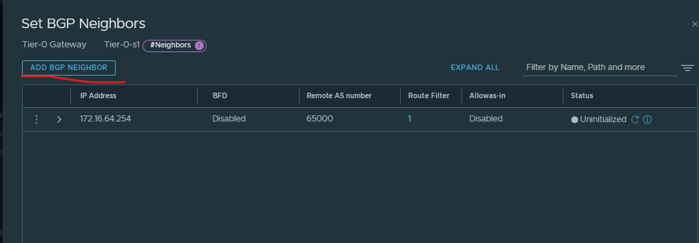
Click add bgp neighbour
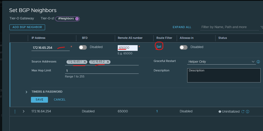
Enter ip of your remote bgp (so your router) > enter bgp of the remote AS > put in the ip address of the sources address ‘interface ip’ matching the same subnet as the router bgp ip > click route filter
Click add route filter.
Ensure IPv4 and enabled > click add
Click apply
Click save.
Click close.

Click save.
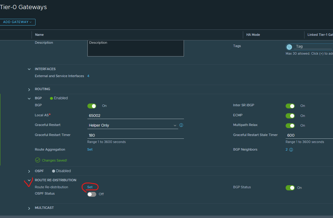
Expand route re-distribution > click set
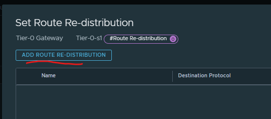
Click add route re-distribution
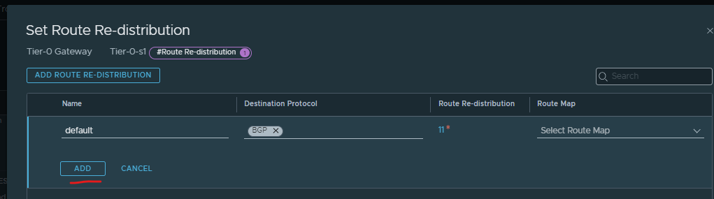
Give it a name > ensure destination protocol is bgp > click set
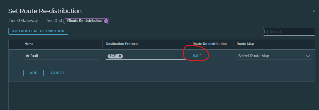
Select the below choices which is most of them > click apply
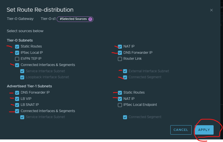
Click add (should be 11)
Click apply
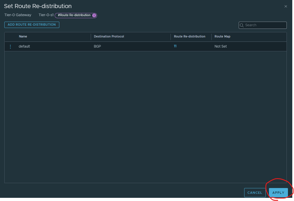
Click save
Click close
CREATE TIER 1
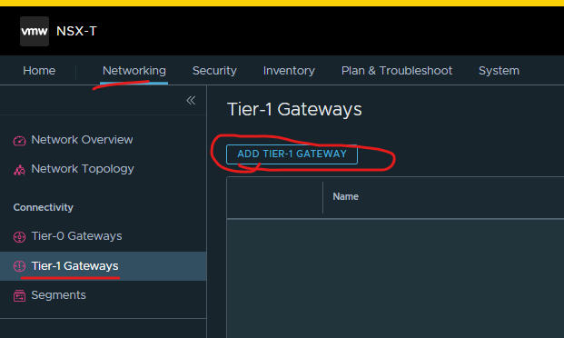
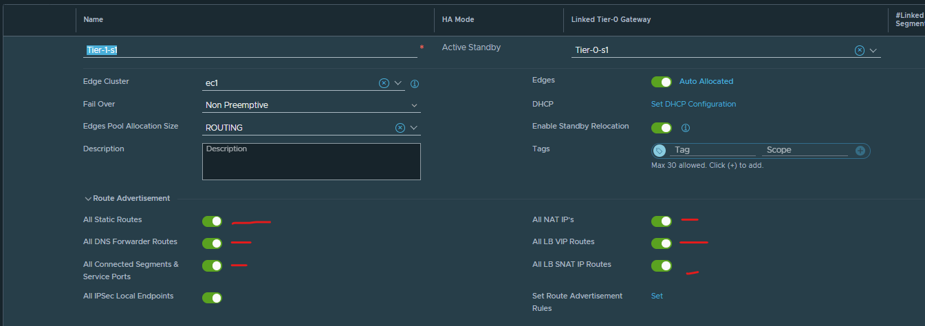
Click networking > Click Tier-1 Gateway > click add tier-1 gateway
Give your tier 1 a name > Link to your tier 0 > Select edge cluster > select ROUTING > enable standby relocation.
(Standby relocation means that if the Edge node where the active or standby logical router is running fails, a new standby logical router is created on another Edge node to maintain high availability.)
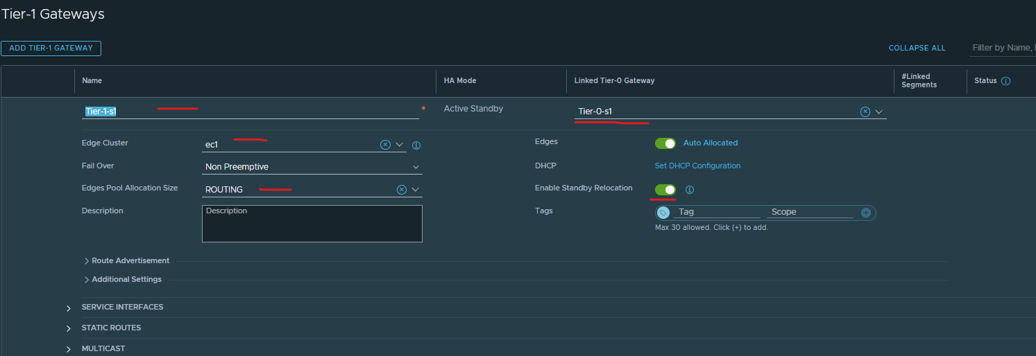
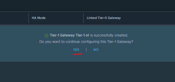
Click save.
Click yes.
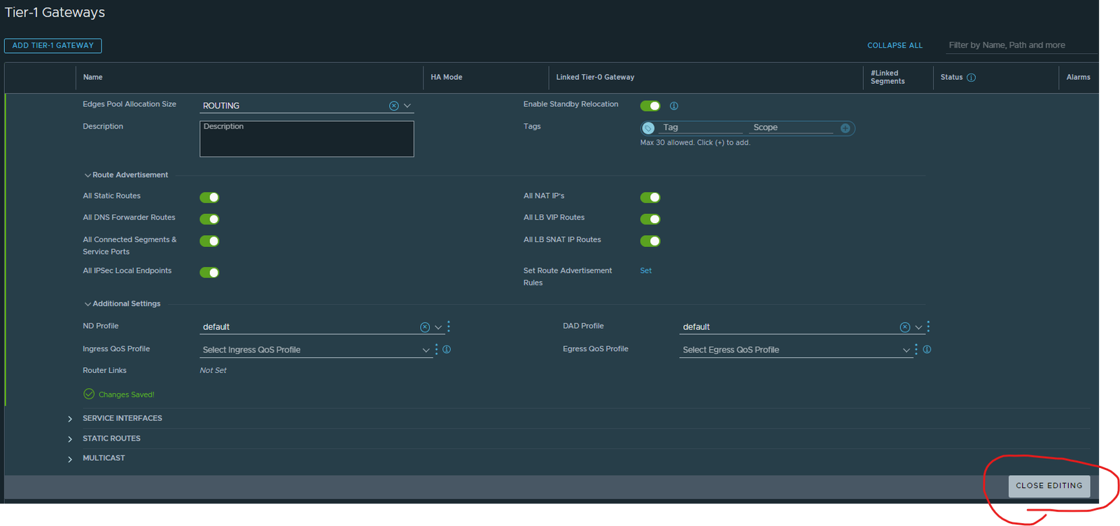
Under route advertisements enable all (should be six not enabled)
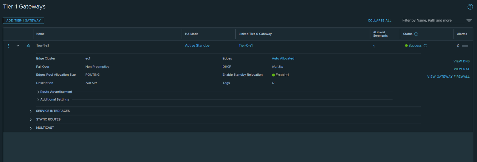
Click save.
Click close
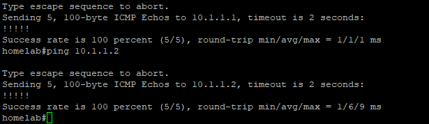
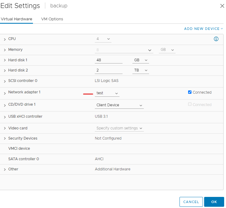
TESTING
Create an overlay segment for testing, add segment to vm, assign ip from that network and ping outside network. (Outside network is my router bpg ip)
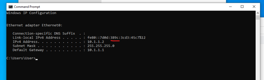

From my router can ping the segment gateway and vm