Now that we have our resource cluster created the next step will be to integrate NSX-T into the resource cluster, deploy our edges and create some OpenStack Specific Objects. Within this section we will conduct the following:
- Deploying the NSX-T Appliance
- Creating IP Pools
- Creating Transport Zones
- Creating Transport Node Profiles
- Creating Edge Profiles
- Creating Edge Nodes
- Creating Edge Clusters
- Creating NSX-T Objects
- Configuring Routing
As with all new installations the first step is to deploy the appliance. In this example we will be deploying NSX-T 3.2.0.1 but in most cases anything above 3.1 will work perfectly fine with VIO. In production workloads we would be looking at deploying 3 managers and connecting them for High Availability but in this instance only a single manager will be deployed.
Configuring The Nested Environment
If your following along from Part 1 you’ll notice that after we deployed the nested resource environment we did not add any networking to the nested vCenter Server. What we will need to do in preparation for NSX-T is to configure a VDS and connect our nested hosts to them.
- Start by logging into the nested vCenter server and navigate to the network options.
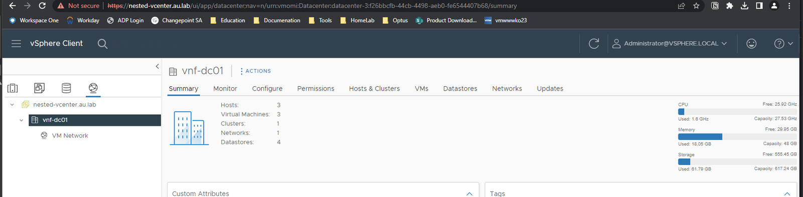
- From here right click the Datacenter and add a new VDS.

- Ill call the switch “nested-switch” and provide it with a port group name of “Management” . Selecting finish will then save the new VDS to the vCenter.

- Following this we will create another port group on the VDS which will be the trunk port group. This will be used for NSX-T. This can be done by right clicking on the VDS and selecting new port group.

- Ill call the port group NSX-Trunk and ensure that it has VLAN Trunking enabled for the port group

- Now we can add our hosts to the VDS. This can be done via right clicking on the VDS and selecting “Add & Manage Hosts”

- From here we want to do the following:
- Add Hosts
- Select All 3 Nested Hosts
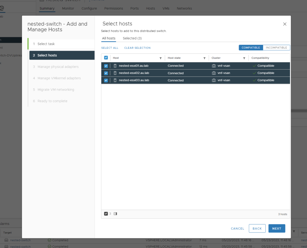
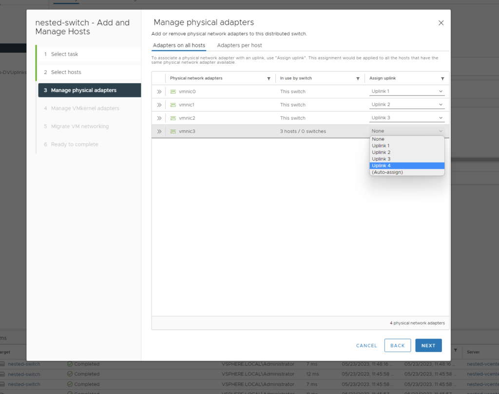
- Add the uplinks to the vmnics
- Assign the vmk0 to the Management Port Group

- Ignore the Migrate VM Networking Tab as we have no VM’s and click “Finish”
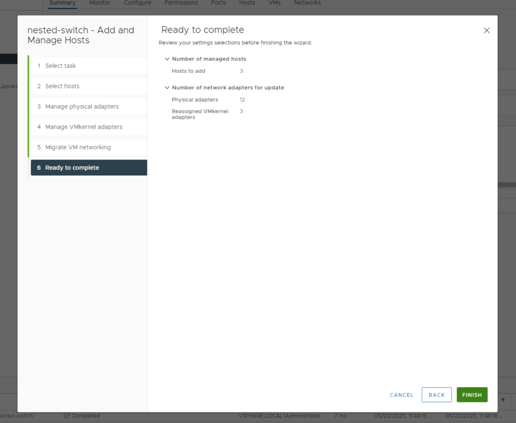
- Once complete you can navigate to the switch configure page followed by topology and you should see the same topology as shown below

Note: If you are encountering errors migrating uplinks and adapters over to the VDS rather than adding all the uplinks at once as shown in step 7c repeat the process and move over each uplink individually.
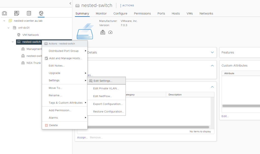
- Finally right click the VDS and select edit settings followed by the advanced menu and confirm that the MTU size for the switch is set to 9000 bytes (Jumbo Frames)

Deploying the OVA
- Login to your management vCenter and deploy the OVA by right clicking on a host or cluster and selecting deploy OVF

- Follow the prompts and enter in the relevant details for the NSX-T Manager when the customization menu appears. For reference we will be following the IP reservation table below:
| FQDN | VLAN | IP |
|---|---|---|
| Management Appliances | ||
| nsx-manager.au.lab | 10 | 10.12.10.17 |
| edge01.au.lab | 10 | 10.12.10.8 |


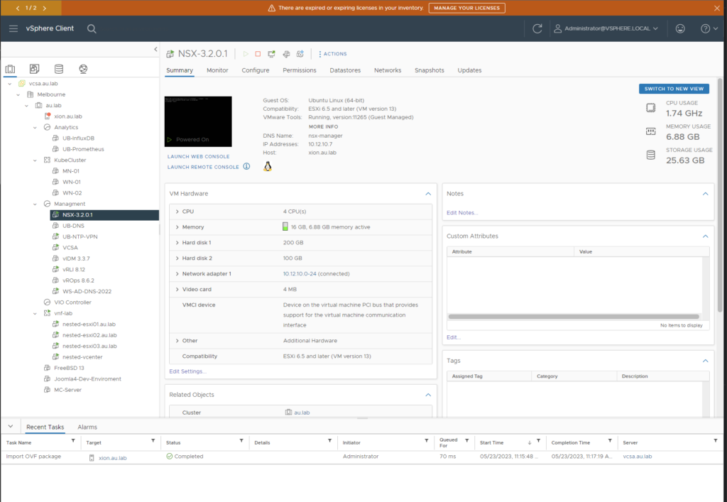
- Once all the appropriate information is filled out select next and wait for the OVA to deploy. Upon completion the VM will automatically boot up and we should see it showing within the vCenter Inventory
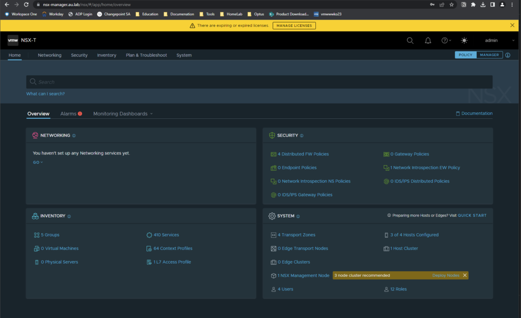
- After the manager has booted up navigate to the FQDN of the appliance and verify that the appliance has successfully instantiated itself and that you are able to login as the admin user. The credentials for this account would have been defined in the prior configuration step.
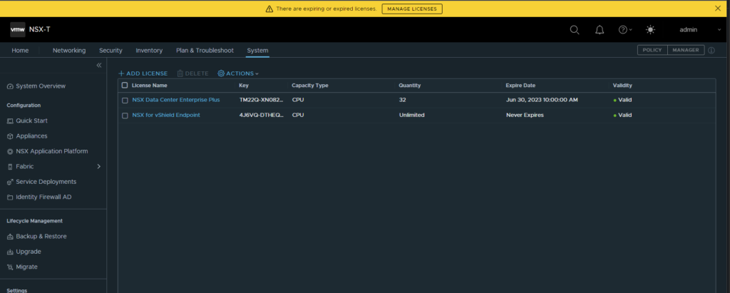
- Selecting the Manage Licences banner at the top of the page or navigating to System —> License will then allow the user to put in there key for NSX-T Datacenter. It’s important this step is taken as without it the user will not be able to create objects.
Configuring NSX-T
To recap in part one there was a number of VLANs that were to be created as part of the pre-req check list. They are as follows
Furthermore VLANs will also need to be created as follows:
- VLAN 10: Management VLAN (10.12.10.0/24)
- VLAN 11: Host TEP Network (10.12.11.0/24)
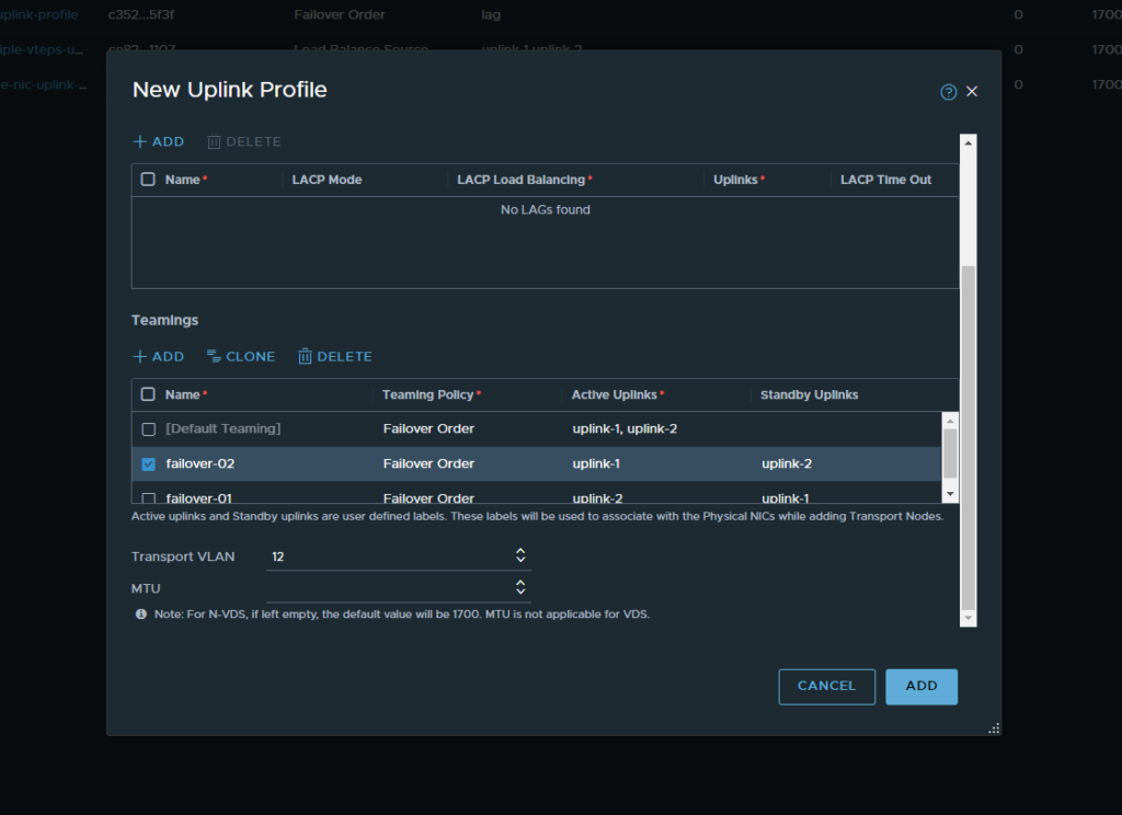
- VLAN 12: Edge TEP Network (10.12.12.0/24)
- VLAN 13: BGP Neighbours (10.12.13.0/24)
- VLAN 14: VIO API Network (10.12.14.0/24)
Within this configuration section we will be using the VLANs that are highlighted in yellow. This will create the backbone of our network.
- To begin navigate to the networking tab and select the IP Address Pool section on the left hand column of NSX-T. Select “Add IP Address Pool” and give it a name. Following that select the “set” button under the subnet column.

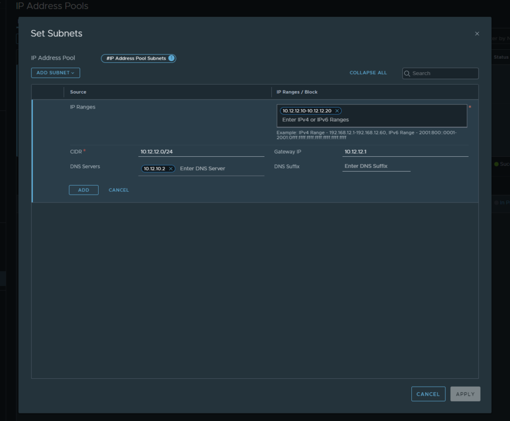
- Here we want to select “add subnet” and then “IP Ranges” From here entire all of the details for the relevant subnet that is in use. For this example we are using (10.12.11.0/24) for out host network. Once completed click “add” then “save” and you should see the TEP pool go into a successful state.

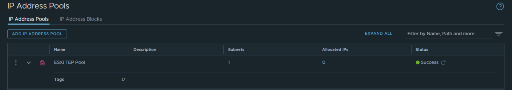
- Now step through the same process but this time with (10.12.12.0/24) for our edge TEP. Once completed there should be 2 IP pools that are ready to be used.

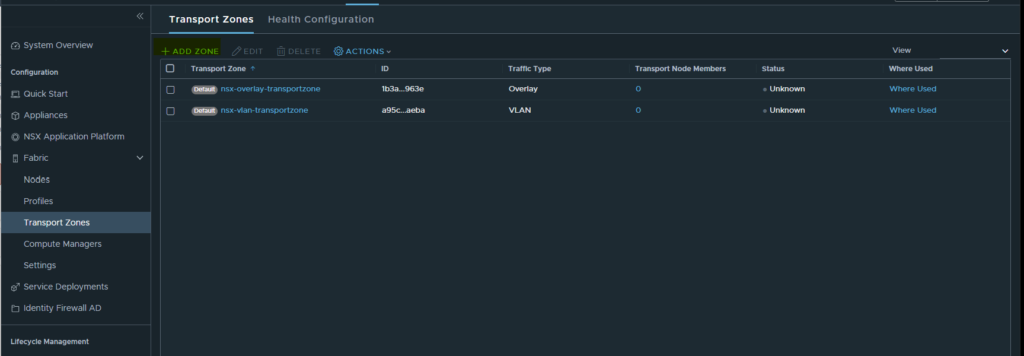
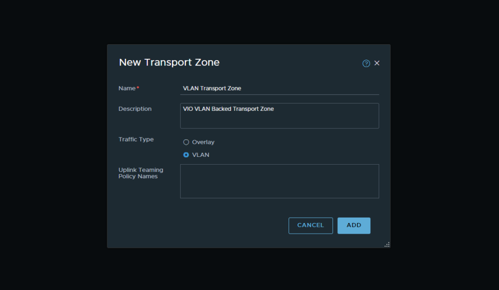
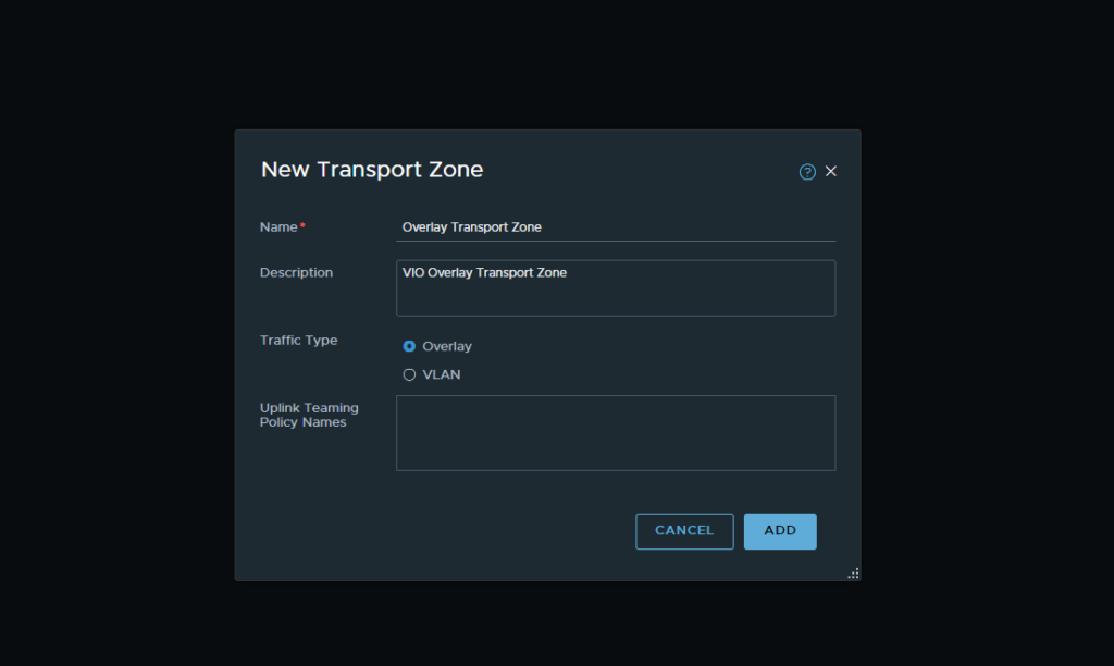
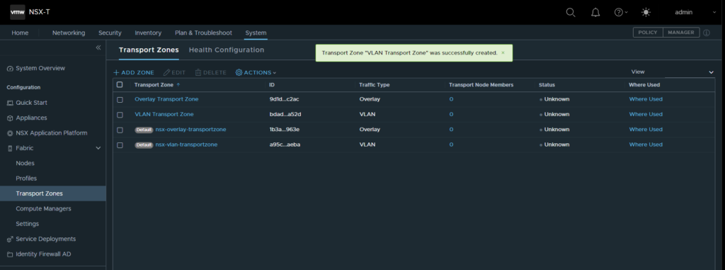
- Next we want to create out transport zones. This can be done via the menu header by selecting System → Fabric → Transport Zones. We will create two transport zones here. One for our overlay network and one for our VLAN backed networks.
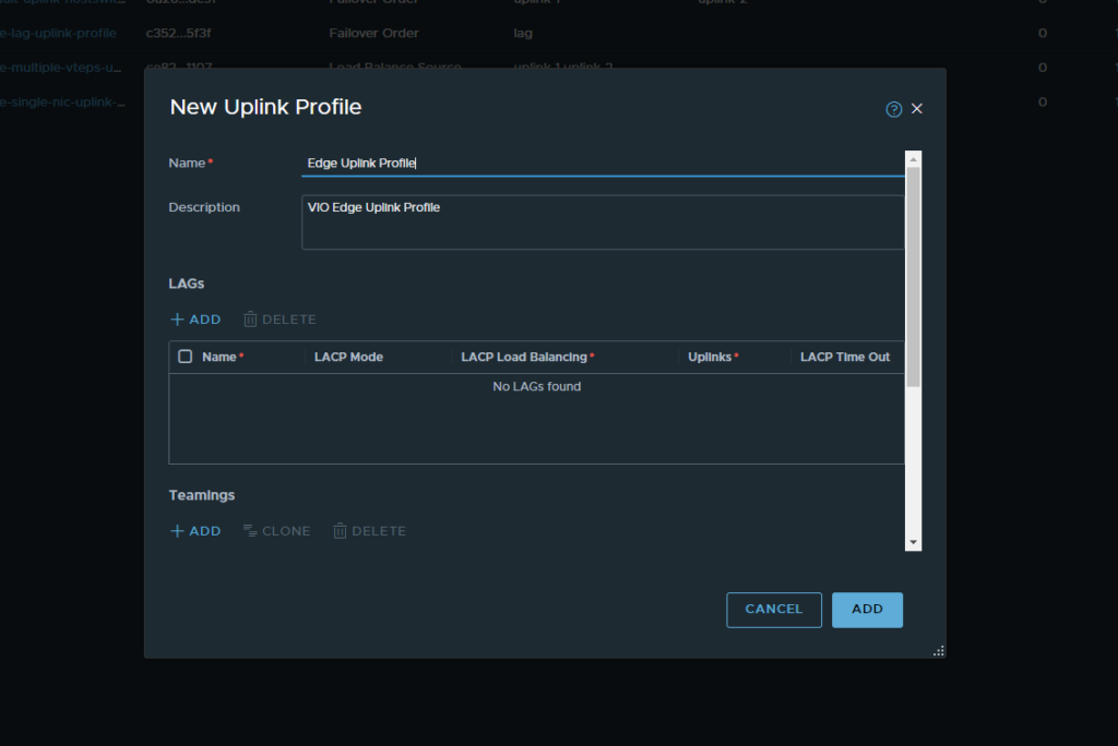
- Once our Transport Zones have been created we can then move onto our uplink profiles. This menu can be found under Fabric → Profiles → Uplink Profiles. Here we will create two uplink profiles. One for our host and one for our edges. In this step we will create our Host Uplink profile


Note: You’ll notice that we are using VLAN 11 as the transport VLAN. This is the same value as our host TEP VLAN which was configured earlier.
- Following this we will create another uplink profile which will be the edge uplink profile. The process will be the same however the transport VLAN will change to be the Edge TEP Network
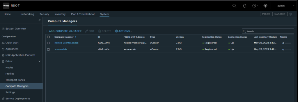
- Now that we have our uplinks created we will add our vCenter’s. Navigate to Fabirc → Computer Managers and add a compute manager. Here we will want to add both our management vCenter and our nested vCenter. Make sure that you are using the administrator account to login or an account which shares the same privilege level.
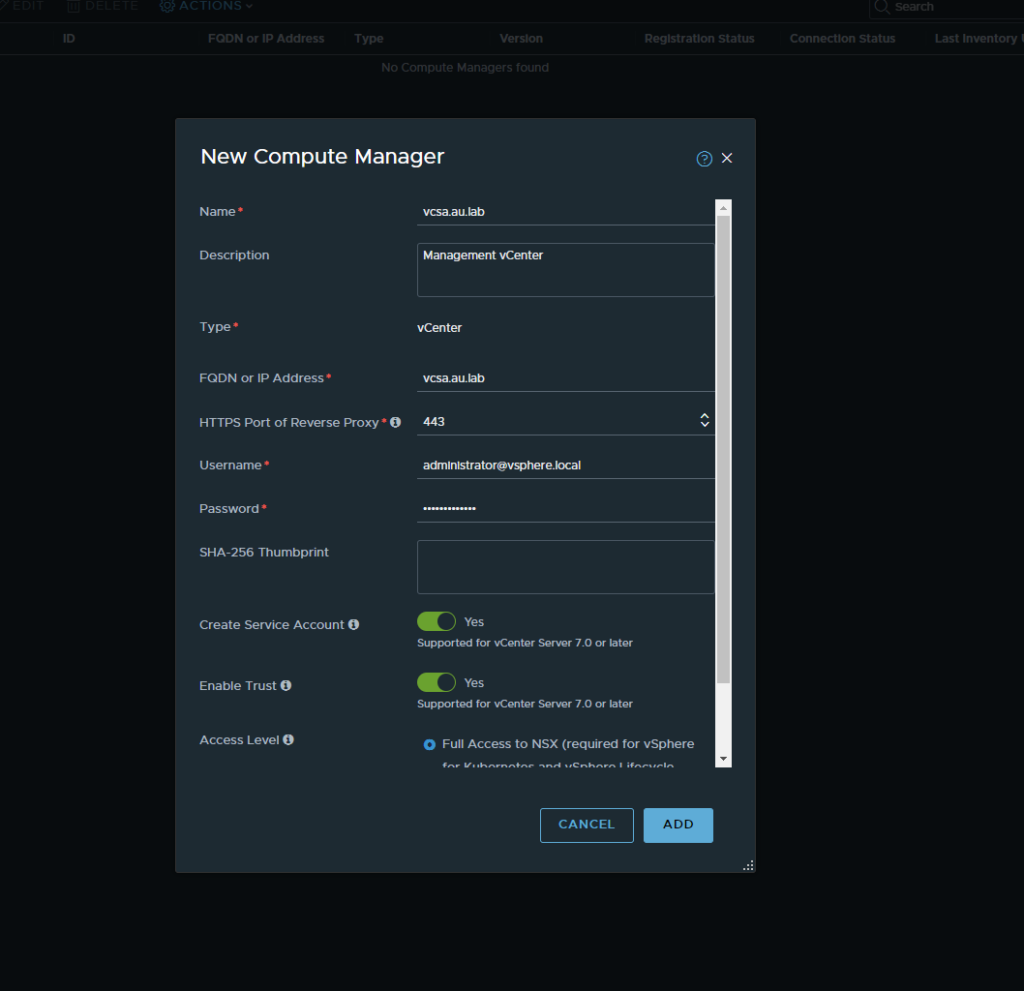

Upon completion both vCenter should show as up within the connection status column.
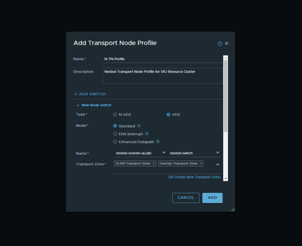
- Now that we have our uplink profiles created, we will now move onto our Transport Node Profiles which will be used to prepare our hosts for NSX-T. Navigate to Fabric → Profiles → Transport Node Profiles and then Add Profile. From there follow

- Now navigate to Fabric → Nodes → Host Transport Nodes and select the drop down to select the nested vCenter instance. Highlight the checkbox for the top of the cluster and select configure NSX.
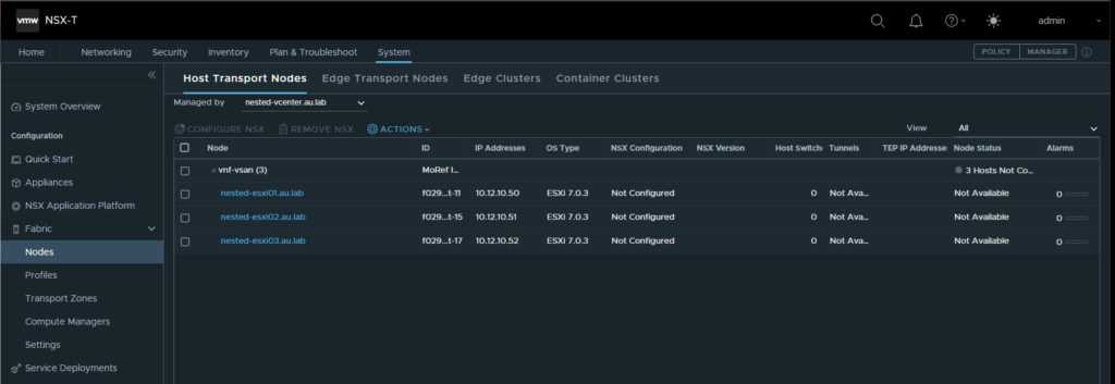
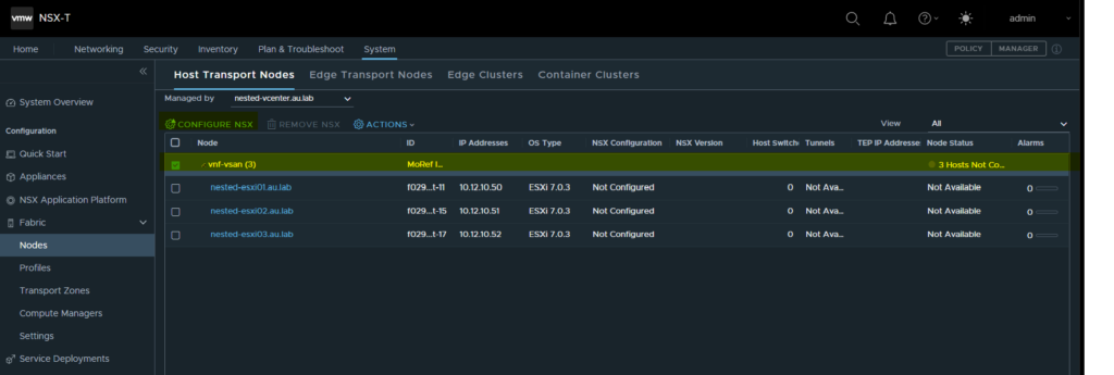
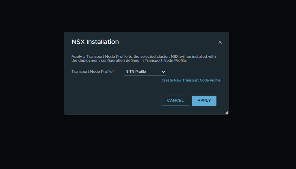
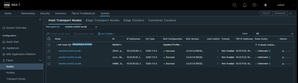
- Select the drop down and select the created transport zone and click apply. This will then go ahead and install the NSX-T Packages on your ESXi hosts. Allow for up to 30mins depending on the speed and age of the hosts. When complete all of the hosts will show as “UP” within the node status.

- Now that we have our uplinks created we will add our vCenter’s. Navigate to Fabirc → Computer Managers and add a compute manager. Here we will want to add both our management vCenter and our nested vCenter. Make sure that you are using the administrator account to login or an account which shares the same privilege level.
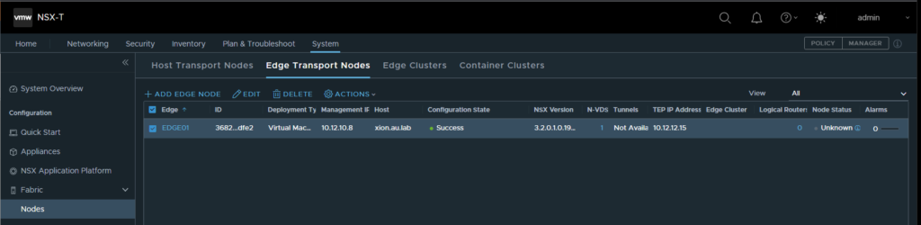
12. Now we will go ahead and create our edge node. For this deployment we will only be deploying a single edge node to save on resources but if you want to expand upon this to create a highly available instance the steps would be the same. Navigate to Fabric → Nodes → Edge Transport Nodes and select Add Edge Node
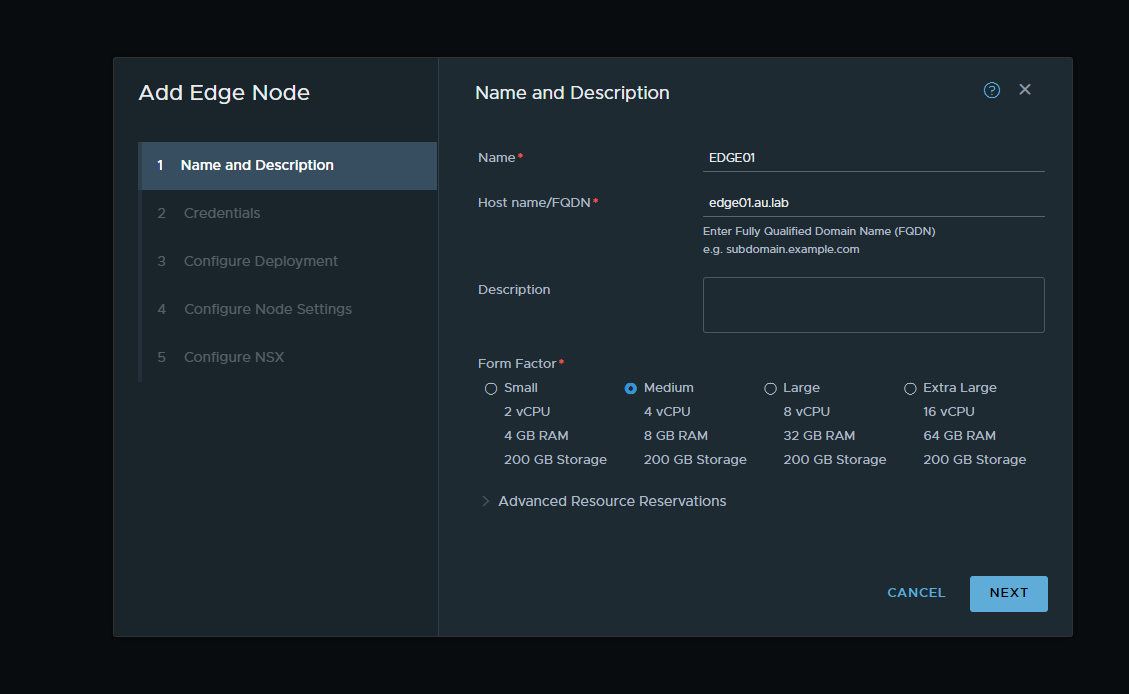

Note: Make sure that you ware placing the edge node on the host vCenter. This will allow for more resources on the nested cluster.
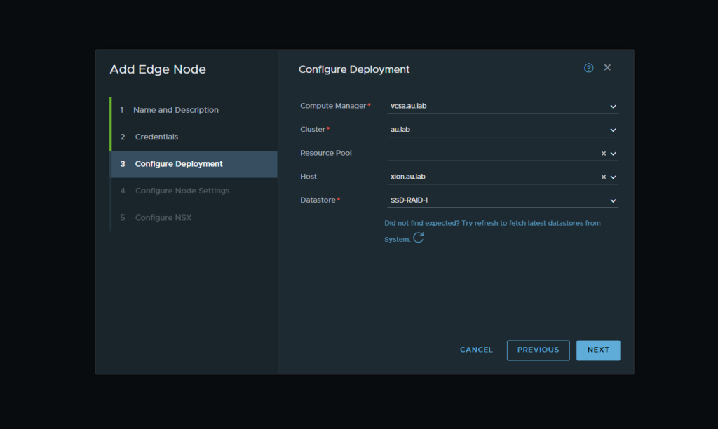
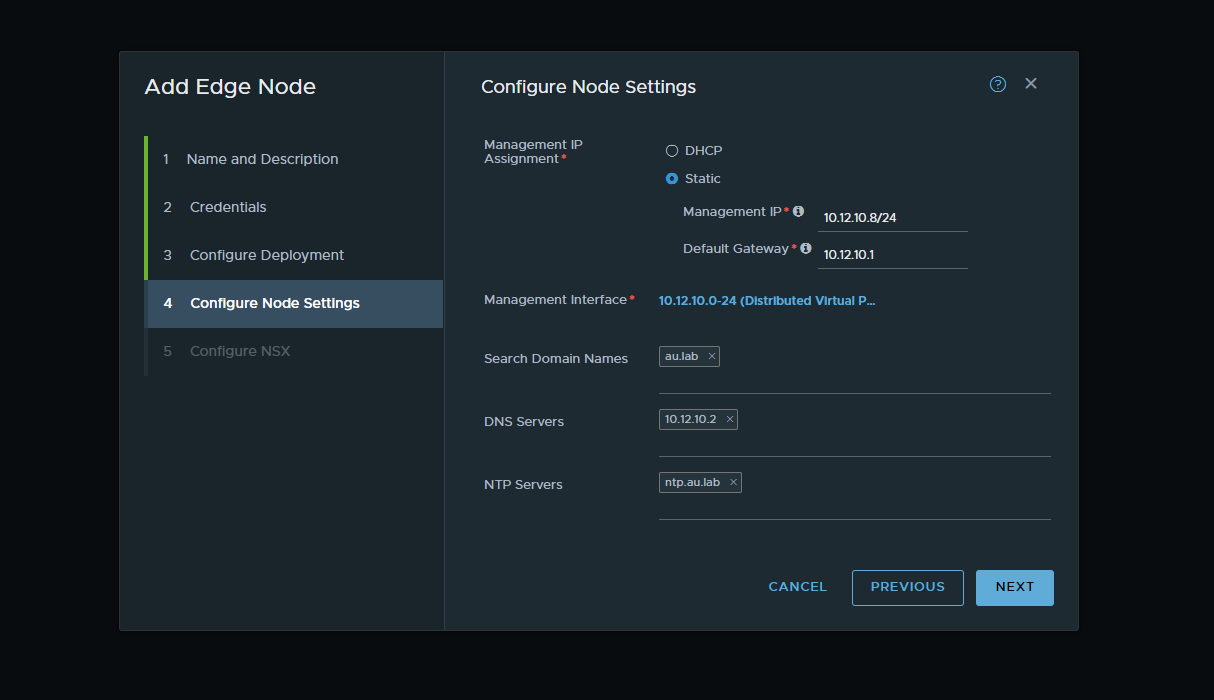
Note; When connecting the two interfaces, ensure that the interfaces are a trunking port group. In the instance below Nested-PG is a trunked port group that was created on the management host.

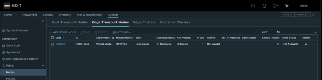
13. Once all the information has been filled out select Finish and the OVA for the edge node will be deployed in the management vCenter. Once the deployment is finished the configuration status will show as “success”
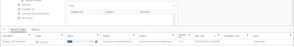
Progress of the OVA deployment can be seen through vCenter
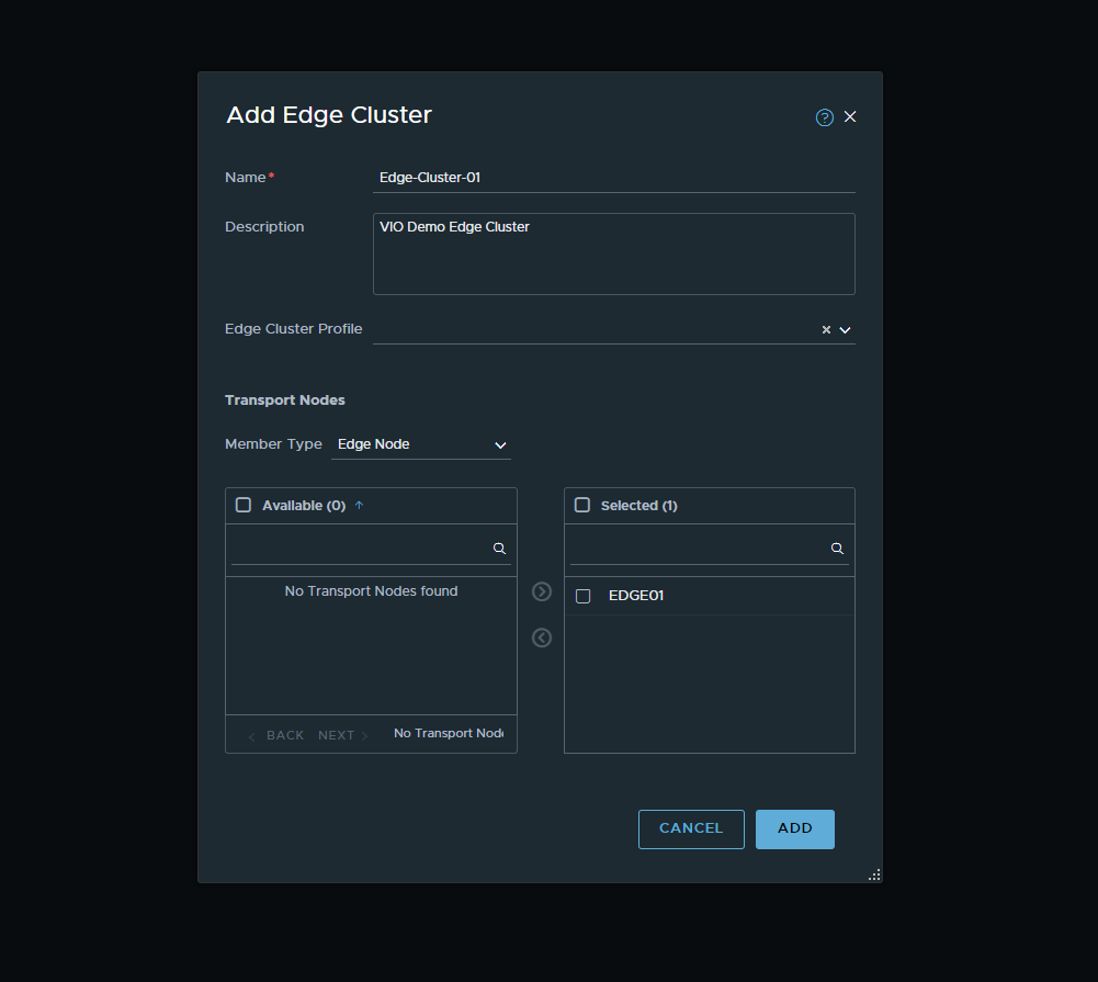
- Following this we can now traverse over to the Edge Clusters Tab and create a new edge cluster. This can be any name but must include the new edge node that was just deployed.
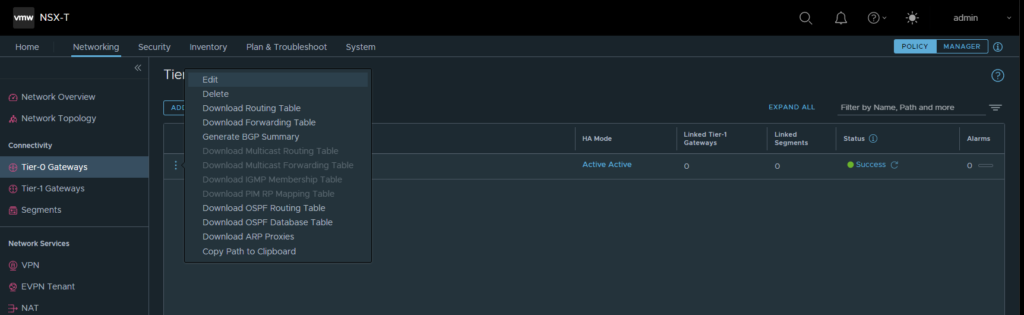
- We can now go ahead and create our routers. Navigate over to Networking → Tier-0 Gateways and select the dropdown to Add A Gateway. From here ensure that the edge cluster that was just created is also selected and then click save.

- We will now go ahead and add some static routes to the router. Select the context menu and then the edit button to open up the edit menu for the router and select the static routes option.
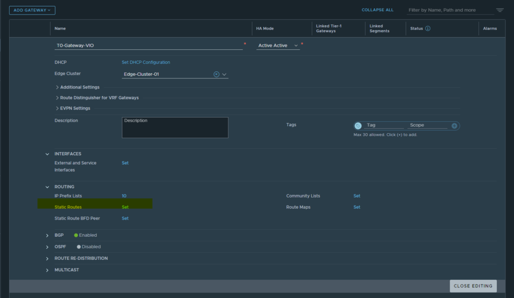
From here we want to add a static route and just make it the default route. We also want to select the Next Hops set button and add the default gateway for our static network.

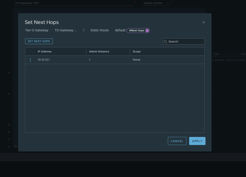
Following this save and close and we now have a static route configured.
- We will now create a VLAN backed segment to create an interface on our T0 router. To do this navigate to Networking → Segments and create a new segment. We will give it a name and ensure that it is running on the VLAN Transport Zone that we created earlier and ensure that the VLAN is the correct VLAN for the external interface.


- Navigate back to the T0 Router menu and edit the existing T0 router and expand the interfaces menu. From here we will select interfaces and add the interface.
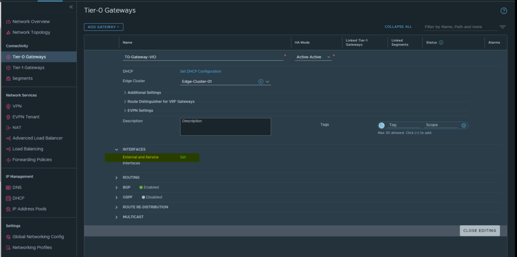
- From here add a new interface and fill in the relevant details using both the edge node and the segment that was just created

Note: If you are using any static routes here you can go ahead and log into your router and point any of the internal subnets back to the edge interface that was created above. For example if we have a segment in the overlay network which uses 172.16.10.2 in your router you would want to have a static route to send anything from 172.16.10.0/24 to the interface on the edge node 10.12.13.10
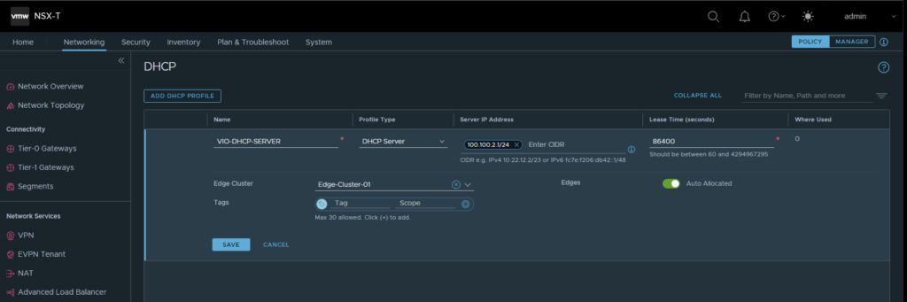
- The final few pieces of the puzzle prior to deploying VIO are the metadata proxy and the DHCP server. The DHCP server can be created directly through NSX-T by navigating to Networking → DHCP and creating a new DHCP Server. This is just an object that OpenStack consumes so the Server IP Address does not actually matter and can just be an arbitrary address.
- Finally to create the Metadata Proxy select the Manager view in the top right of the NSX GUI and navigate to Networking → DHCP → Metadata Proxies
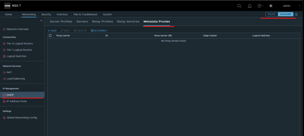
- Select the add button and populate the menu with the required information. The Nova Server URL refers to the private API address that was created earlier in Part 1 and the secret is simply a password that we can create for use in the OpenStack deployment.
VIO Records vio-vip-public.au.lab 14 10.12.14.10 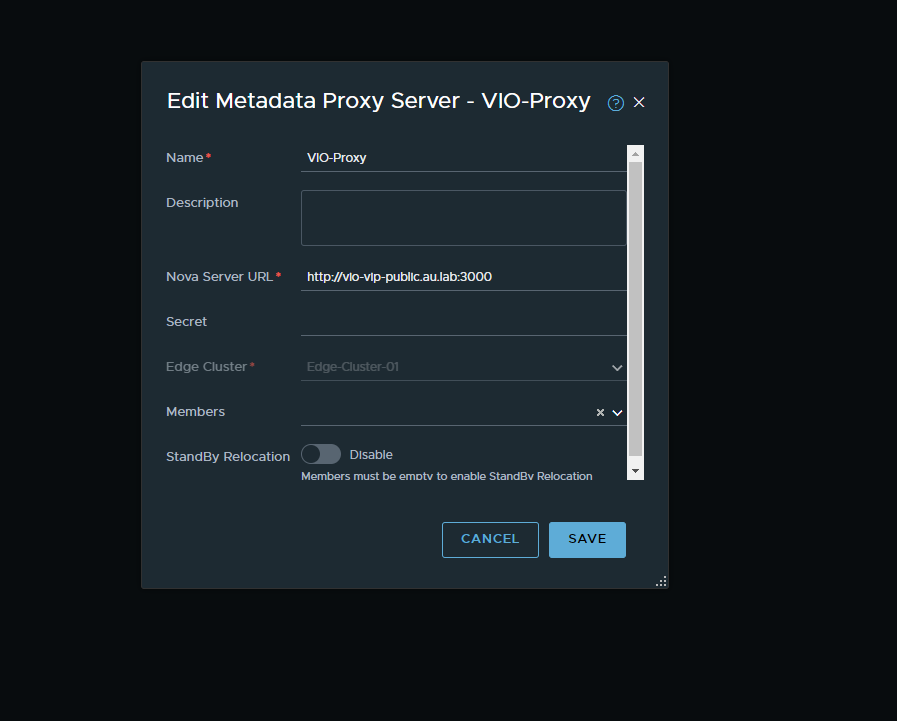
- Next we want to create out transport zones. This can be done via the menu header by selecting System → Fabric → Transport Zones. We will create two transport zones here. One for our overlay network and one for our VLAN backed networks.
Finally once this proxy has been created hit the add button and we are complete with the NSX-T setup. In the next chapter we will look at how to deploy the VIO OVA along with deploying an OpenStack instance.